


unpacking and
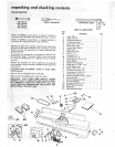
TABLE OF LOOSE PARTS
The Following Parts Are included With
Model 113.206931 Only
Item
No,
A
8
C
D
E
F
G
G
G
H
J
K
K
L
M
N
= JL _ , LLUH,H,
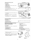
checking contents
Description Qty.
Leg .............................. 4
End Stiffener ....................... 2
Side Stiffener ...................... 4
Motor Support ..................... 1
Motor ............................ 1
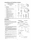
Package of Miscellaneous Small Parts,
No. 67035, Consisting of the Following:
Cord Clip .......................... 2
Hex Nut, 1/4 in. - 20
(approx. die, of hole 1/4 in.) .......... 40
Hex Nut, 5/I6 in. - 18
(approx. alia. of hole 5/1 6 in.) ......... 7
Hex Nut, 1/2 in. - 13
(approx. die. of hole 1/2 in.) .......... 8
Truss Hd, Screw, !/4 in. - 20 x 5/'8 in.
long. (Top of screw is rounded) ........ 40
Flat Washer (dia, of hole 11/32 in.) ...... 7
Lockwasher, 1/4 in. External Type
(approx. dia. of hole 1/4 in.) .......... 40
Lockwasher, 5/1 6 in. External Type
(approx. die. of hole 5/16 in,) ......... 7
Carriage Boh, 5/16 in. - 18 x 3/4 long ... 3
Leveling Foot ...................... 4
Hex Hd. Screw, 5/16 in. - 18 x 2 in ..... 3
A
C
assembly
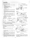
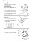
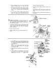
ASSEMBLING STEEL LEGS
NOTE: Steel Legs are furnished with Model 11 3.206931.
From among the loose parts, find the following Hardware:
40 Truss Head Screws, 1/4-20 x 5/8
40 Lockwashers, 1/4-External
40 Hex Nuts, 1/4-20
8 Hex Nuts, 1/2q3
4 Leveling Feet
1. Assemble two (2) Side Stiffeners together using four (4)
1/4-20 Truss head screws, Iockwasher and nuts. Make
two (2) Side Stiffener assemblies.
The End Stiffeners are placed on top and at each end of
Side Stiffener assemb)ies as shown. Align holes, letter
coded "'B'" in Side Stiffeners and End Stiffeners and
then insert 1/4-20 Truss head screws through the 9/32
diameter holes and install Iockwashers and nuts and
then tighten.
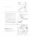
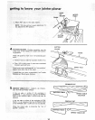
2. Assemble the four (4) Legs to the Side and End
Stiffeners using 1/4-20 screws, Iockwashers and nuts as
shown,
3. Assemble the Motor Support to the Legs with 1/4,20
screws, ]ockwashers and nuts. Motor Support can be
assembled to either end of Leg set.
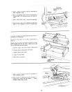
4. Install leveling feet as shown. To )eve,] Leg Set, loosen
nut on inside of leg and turn nut on the outside to raise
or lower feet. Adjust all four leveling feet, if necessary,
and then tighten nuts on the inside of leg.
NOTE: These levelers are not intended for height
adius_ment,
F
J K
L M
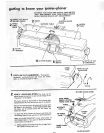
TRUSS HD. SCREW END STIFFENER
1/4-2i X 51//84EXTERNAL 1
END \ LOCKWASHER _
STIFFENER !_ _//_ 1/4_20 HEX NUT _"
IDE STIFFENERS
N