


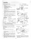

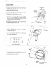
iNSTALLING SLIDING GUARD
i :
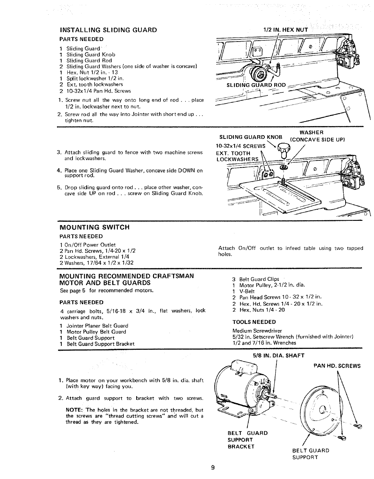
1/2 IN. HEX NUT
PARTS NEEDED
I Sliding Guard _
1 Sliding Guard Knob
1 Sliding Guard Rod
2 Sliding Guard Washers (one side of washer is concave)
1 Hex. Nut 1/2 in. _ 13
t Spait toc'kwasher I/2 in.
2 Ext, tooth tockwashers
2 10-32xl/4 Pan Hd. Screws
SLI DIt'_'GGUARD
1. Screw nut all the way onto long end of rod . . . place
1/2 in. Iockwasher next to nut.
2. Screw rod alt the way into Jointer with short end up...
tighten nut.
3, Attach sliding guard to fence with two machine screws
and Iockwashers.
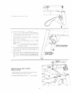
SLIDING GUARD KNOB
10-32xl/4 SCREWS'_
EXT. TOOTH
LOCKWASHERS
ii ii lul ii i ill i,u,nu, u,,,,
WASH ER
(CONCAVE SIDE UP)
4. Place one Sliding Guard Washer, concave side DOWN on
support rod,
5, Drop sliding guard onto rod.., place other washer, con-
cave side UP on rod . . . screw on Sliding Guard Knob.
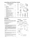
MOUNTING SWITCH
PARTSNEEDED
1 On!Off Power Outlet
2 Pan Hd. Screws, 1/4-20 x t/2
2 Lockwashers, External 1/4
2 Washers, 17/64 x 1/2 x 1/32
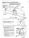
MOUNTING RECOMMENDED CRAFTSMAN
MOTOR AND BELT GUARDS
Seepage5 for recommendedmotors.
PARTS NEEDED
4 carriage bolts, 5/16-t8 x 3/4 in., flat washers, lock
washers and nuts.
1 Jointer Planer Belt Guard
1 Motor Pulley Belt Guard
I Belt Guard Support
! Belt Guard Support Bracket
i ii i,,pl
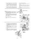
t. Place motor on your workbench with 6/8 in. dia. shaft
(with key way) facing you.
2. Attach guard support to bracket with two screws.
NOTE: The holes in the bracket are not threaded, but
the screws are "thread cutting screws" and will cut a
thread as they are tightened.
Attach On/Off outlet to infeed table using two tapped
holes.
5/8 IN. DIA. SHAFT
TOOLS NEEDED
Medium Screwdriver
5/32 in, Setscrew Wrench (furnished with Jointer)
t/2 and 7/t6 in. Wrenches
BELT GUARD
SUPPORT
BRACKET
BELT GUARD
SUPPORT
PAN HD. SCREWS
3 Belt Guard Clips
1 Motor Pulley, 2q/2 in. dia.
1 V-Belt
2 Pan Head Screws 10- 32 x I/2 in,
2 Hex, Hd. Screws 1/4 - 20 x t/2 in,
2 Hex. Nuts t/4- 20