


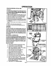
SWITCH REPLACEMENT
See Figures 15 & 16.
1. UNPLUG YOUR ROUTER.
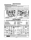
MAINTENANCE
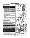
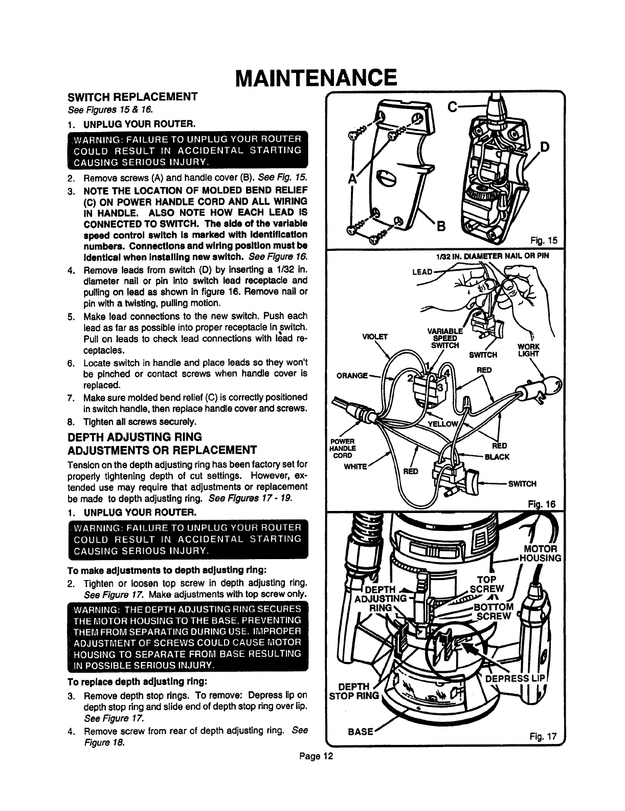
2. Remove screws (A) and handle cover (B). See Fig. 15.
3. NOTE THE LOCATION OF MOLDED BEND RELIEF
(C) ON POWER HANDLE CORD AND ALL WIRING
IN HANDLE. ALSO NOTE HOW EACH LEAD IS
CONNECTED TO SWITCH. The side of the variable
speed control switch Is marked with Identification
numbers. Connections and wiring position must be
Identical when Installing new switch. See Figure 16.
4. Remove leads from switch (D) by inserting a 1/32 in.
diameter nail or pin into switch lead receptacle and
pulling on lead as shown in figure 16. Remove nail or
pin with a twisting, pulling motion.
5. Make lead connections to the new switch. Push each
lead as far as possible into proper receptacle in switch.
Pull on leads to check lead connections with I_ad re-
ceptacles.
6. Locate switch in handle and place leads so they won't
be pinched or contact screws when handle cover is
replaced.
7. Make sure molded bend relief (C) iscorrectly positioned
in switch handle, then replace handle cover and screws.
8. Tighten all screws securely.
DEPTH ADJUSTING RING
ADJUSTMENTS OR REPLACEMENT
Tension on the depth adjusting ring has been factory setfor
propedy tightening depth of cut settings. However, ex-
tended use may require that adjustments or replacement
be made to depth adjusting ring. See Figures 17- 19.
1. UNPLUG YOUR ROUTER.
To makeadjustments to depth adjusting ring:
2. Tighten or loosen top screw in depth adjusting ring.
See Figure 17. Make adjustments with top screw only.
To replacedepth adjusting ring:
. Removedepthstoprings. To remove: Depresslipon
depthstopringand slideendofdepthstopringoverlip.
See Figure17.
Removescrewfrom rear of depthadjustingring, See
Figure18.
Page 12
4.
VIOLET
POWER
HANDLE
CORD
B
1/32 IN. DIAMETER NAIL OR PIN
VARIABLE
SPEED
SWITCH LIGHT
RED