


Df[\cN(/)+('?pYi`[KXYc\JXn
-61-
J<IM@:<
The trunnion and motor assembly could fall and crush
your hands or arms if the trunnion mounting cap
screws are loosened too much during the following
steps. DO NOT remove the cap screws that secure
the trunnions to the table or loosen them more than
1
1
⁄2 turns!
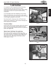
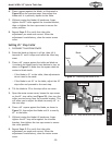
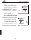
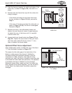
7. To adjust the table, loosen the two cap screws that
secure the rear trunnion to the underside of the
table 1–1
1
⁄2 turns (see Figure 96), and slightly tap
the trunnion with the dead blow hammer in the
needed direction.
8. Tighten the two cap screws, then repeat Steps 2–5
to re-check the slot-to-blade parallelism.
— If the measurement is the same from front-to-
back, skip ahead to Step 11.
— If the adjustments you made in Step 7 were not
enough to adjust the miter slot parallel to the
blade, continue to Step 9.
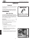
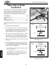
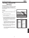
9. Loosen the two cap screws that secure the front
trunnion to the underside of the table (see
Figure 97) and tap the trunnion in a similar manner
as you did in Step 7.
10. Tighten the two cap screws and recheck the miter
slot-to-blade parallelism.
— If the blade tip measurement is the same on both
sides, continue to Step 11.
— If the adjustments you made in Step 9 were not
enough to adjust the miter slot parallel with
the blade, continue adjusting the front and rear
trunnions as needed until the miter slot and blade
are parallel.
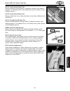
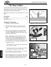
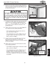
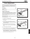
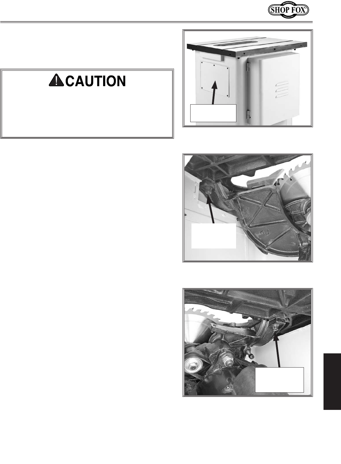
Figure 95. Location of the rear trunnion
access panel.
Rear Trunnion
Access Panel
Figure 96. Location of the rear trunnion
cap screw (1 of 2).
Rear Trunnion
Cap Screw
(1 of 2)
6. Remove the six button head cap screws that secure
the rear trunnion access panel (see Figure 95), then
remove the panel and open the motor access cover
to reach the trunnions.
Figure 97. Location of the front trunnion
cap screw (1 of 2).
Front Trunnion
Cap Screw
(1 of 2)