


-8-
Mfg. Since 10/09
SB1363-64/SB1367-68
PREPARATION
Vertical Installation
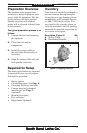
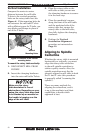
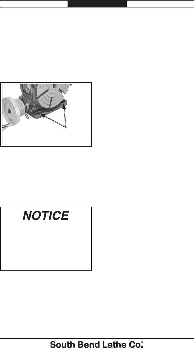
Compare the center to center
distance between the mill table
T-slots to the vertical mounting
holes on the rotary table foot (see
Figure 4). If the mounting holes do
not intersect the mill table T-slots
with sufficient space for T-bolts, use
step blocks and clamps in place of
one of the T-bolts.
Figure 4. Locations of the vertical
mounting holes.
Vertical
Mounting Holes
To mount the rotary table vertically:
1. DISCONNECT MILL FROM
POWER!
2. Insert the clamping hardware
into the outer mill table T-slots.
Make sure the rotary
table handwheel is free of
obstructions. Depending on your
setup, the rotary table may need
to be blocked up or mounted so
the handle is hanging over the
edge of the mill table.
3. Place the rotary table on the
mill table so that you can use
the clamping hardware to secure
it in the next step.
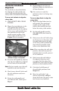
4. Placethemachinist'ssquare
along the front of the mill table
and the machined side of the
rotary table foot, square the
rotary table to the mill table,
then fully tighten the clamping
hardware.
5. Perform the Vertical
Installation Alignment
procedure as instructed on
Page 10.
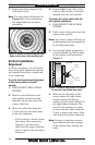
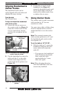
Aligning to Spindle
Centerline
Whether the rotary table is mounted
horizontally or vertically, you must
align the rotary table centerline
to the mill spindle centerline to
achieve quality results. Also, the
spindle centerline must first be
properly aligned to mill table in both
the X- and Y- axis (this procedure
is generally called "tramming the
spindle").
There are many methods for
aligning the centerlines, and it
is up to the machinist and their
capabilities to decide which
approach is best.