


-10-
Mfg. Since 10/09
SB1363-64/SB1367-68
PREPARATION
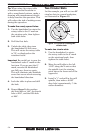
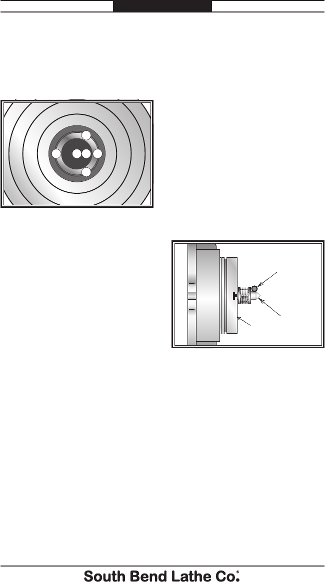
7. Repeat the above steps for the
mill table Y-axis.
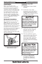
Note: Use the pattern illustrated in
Figure 6 to aid in positioning
the edge finder for the above
procedure.
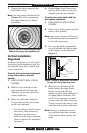
Figure 6. Pattern of positioning the edge
finder to the rotary table spindle bore.
1
2
3
4
5
6
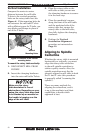
Vertical Installation
Alignment
In these procedures, you will verify
the rotary table alignment with the
mill spindle from front to back and
to its centerline.
To verify the front-to-back alignment
of the rotary table to the mill
spindle:
1. DISCONNECT MILL FROM
POWER!
2. Mount a test indicator to the
mill spindle and position the
indicator tip on one end of the
rotary table face.
3. Move the mill table along the
Y-axis and note any deviations
in the test indicator.
— If a deviation is found, loosen
the rotary table mounting
fasteners, tap the rotary
table into the proper position,
then re-tighten the mounting
fasteners.
4. Repeat Step 3 until the entire
rotary table surface is correctly
aligned with the mill spindle.
To center the rotary table with the
mill spindle centerline:
1. DISCONNECT MILL FROM
POWER!
2. Fully seat a lathe center into the
rotary table spindle.
Note: Any center runout will have to
be determined and accounted for
in the following steps.
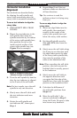
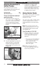
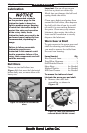
3. Use an edge finder mounted in
the mill spindle to find the edge
of the center, as illustrated in
Figure 7.
Figure 7. Using an edge finder and center
to align the rotary table (top view).
Edge
Finder
Lathe
Center
Rotary
Table
Top View
4. Measure the diameter of the
center where the edge finder
makes contact, divide this
number in half, then add half of
the edge finder diameter. The
result is the amount you need
to move the mill table along the
Y-axis to center the rotary table
with the mill spindle centerline.
Note: Be sure to take into account
any backlash and any rounout
of the center when moving the
table.