


-11-
SB1363-64/SB1367-68Mfg. Since 10/09
OPERATION
To reduce the risk of serious
injury when using this
equipment, read and understand
this entire manual before
beginning any operations.
Controls & Components
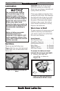
Refer to Figure 8 and the following
descriptions to become familiar with
the controls and components used to
operate the rotary table.
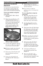
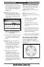
Figure 8. Rotary table controls and
components (Model SB1367 shown).
A
B
C
E
D
F
G
H
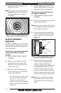
C. Vernier Scale: Displays the
amount of table rotation with
a resolution of 10" (ten arc
seconds).
D. Rotation Scale: Displays the
table position in whole degrees.
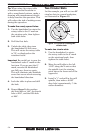
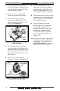
E. Table Locks: When fully
tightened, keep the table from
rotating to reduce the strain
on the gears during operation.
When cutting circular slots, a
slight drag can be applied with
the table locks to help reduce
chatter caused by gear backlash.
F. Spindle Bore: Holds a center to
support a workpiece for dividing
work. Also, used in rotary table
alignment with the mill spindle
centerline.
G. Backlash Adjustment
Lock: Secures the backlash
adjustment ring in place.
H. Backlash Adjustment Ring
Lever: Conveniently controls the
backlash adjustment ring for
adjusting the backlash between
the gears.
When rotated completely
clockwise, the backlash
adjustment ring disengages the
gears so that the table can be
rotated by hand.
Note: The Model SB1368 uses
a knurled ring instead of a
lever.
A. Handwheel: Rotates the table
when the gears are engaged.
B. Handwheel Scale: Displays the
amount of the table rotation
witharesolutionof1'(onearc
minute) and also in 1° marks.
One complete revolution of the
handwheel rotates the table 4°.