


For Machines Mfg. Since 3/11 Turn-Nado
®
EVS Lathes
-59-
OPERATION
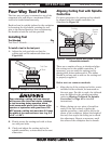
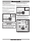
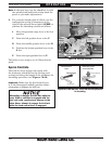
4. Loosen the pivot arm hex nut shown in
Figure 77, then swing the pivot arm to the
left so that the 44T/56T gears are away from
the 57T gear. Hand tighten the hex nut to
keep the arm in place.
As you remove and replace end gears, use
a stiff brush and mineral spirits to clean
away the debris and grime from them, then
re-lubricate them as instructed in End Gears
on Page 74.
5. Making sure to keep the shaft key firmly
seated, remove the spacer and the 57T gear,
then re-install them as follows:
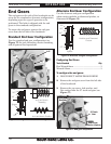
— For the standard end gear configuration,
slide the 57T gear on first, then the spacer
on the outside.
— For the alternate end gear configuration,
slide the spacer on first, then the gear.
6. Re-install the cap screw, lock washer, and
flat washer you removed in Step 3 to secure
the spacer and 57T gear. Do not overtighten.
7. Slide the pivot arm back so that either the
44T or the 56T meshes with the 57T gear,
then retighten the pivot arm hex nut.
Note: Make sure to keep approximately 0.002"
play between the gears.
8. Replace and secure the end gear cover before
re-connecting the lathe to power.
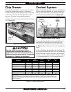
The following subsections describe how to use
the threading controls and charts on this lathe.
If you are unfamiliar with the process of cutting
threads on a lathe, we strongly recommend that
you read books, review industry trade magazines,
or get formal training before doing any threading
projects.
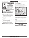
Headstock & Gearbox Threading
Controls
The threading charts on the headstock face
display the settings for metric and inch
threading, and modular and diametral pitches.
For inch or metric threads, use the standard end
gear configuration. For modular or diametral
pitches, use the alternate configuration
Use the controls on the lathe and follow along
with the example below to better understand
how to set up the lathe for the desired threading
operation.
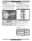
Example: Metric Thread Pitch of 2.5mm
1. Make sure the end gears are in the standard
configuration, which is used for all metric
threading (refer to End Gears on Page 58
for detailed instructions).
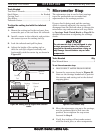
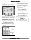
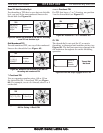
2. Locate the line in the metric thread chart
that lists the setting for 2.5mm threads, as
illustrated in Figure 78.
Threading Controls
Figure 78. Metric thread chart.
Metric Thread
Width of 2.5mm