


For Machines Mfg. Since 3/11 Turn-Nado
®
EVS Lathes
-81-
SERVICE
Half Nut Adjustment
The clamping pressure of the half nut is fully
adjustable with a gib that can be loosened or
tightened by two set screws. Use this procedure
to adjust the half nut if it becomes loose from
wear, or it is too tight for your preferences. A
half nut that is too loose will make it difficult
to produce accurate work. A half nut that is too
tight will increase the rate of wear on itself and
the leadscrew.
Tool Needed: Qty
Hex Wrench 3mm .................................................1
To adjust the half nut:
1. Disengage the half nut, then remove the
thread dial.
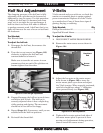
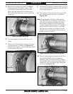
2. Turn the two set screws (see Figure 123)
clockwise to tighten the half nut and
counterclockwise to loosen it.
Make sure to turn the set screws in even
amounts so that one end of the gib does not
become tighter than the other.
3. Engage/disengage the half nut several times
and notice how it feels. The half nut is
correctly adjusted when it has a slight drag
while opening and closing. The movement
should not be too stiff or too sloppy.
4. Repeat Steps 2–3, if necessary, until you are
satisfied with the half nut pressure.
5. Re-install the thread dial.
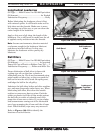
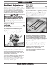
Figure 123. Half nut gib adjustment.
Set
Screws
V-Belts
V-belts stretch and wear with use, so check the
tension on a monthly basis to ensure optimal
power transmission. Replace all of the V-belts
as a matched set if any of them show signs of
glazing, fraying, or cracking.
Tools Needed: Qty
Phillips Screwdriver #2 ........................................1
Open End Wrench 24mm......................................1
To adjust the V-belts:
1. DISCONNECT LATHE FROM POWER!
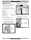
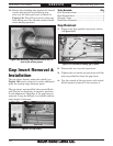
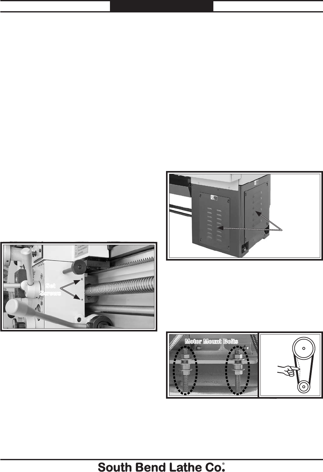
2. Remove the motor access covers shown in
Figure 124.
4. Tighten the hex nuts against both sides of
the motor mount plate to prevent it from
moving out of adjustment during operation,
then re-install the access covers.
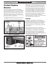
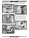
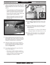
Figure 125. V-belt adjustment.
Pulley
Deflection
Pulley
Motor Mount Bolts
3. Adjust the hex nuts on the motor mount
bolts shown in Figure 125 to move the
motor mount plate up or down and adjust
the V-belt tension. When correctly tensioned,
each belt should have about
3
⁄4" deflection
when pressed firmly (see Figure 125).
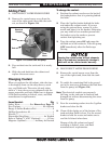
Figure 124. Locations of motor access covers.
Access
Covers
Headstock
End