


-80-
For Machines Mfg. Since 3/11
Turn-Nado
®
EVS Lathes
SERVICE
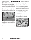
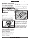
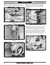
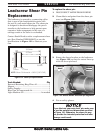
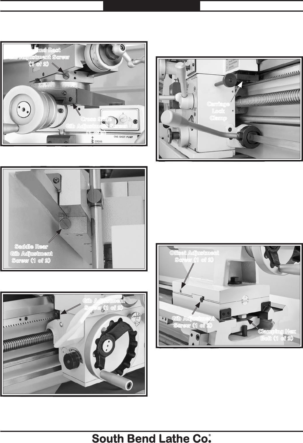
Figure 118. Compound and cross slide gib adjustment
screws.
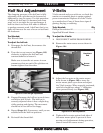
Compound Rest
Gib Adjustment Screw
(1 of 2)
Cross Slide
Gib Adjustment Screw
(1 of 2)
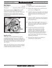
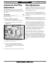
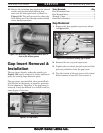
Note: Remove the thread dial body and the
carriage lock clamp to access the saddle gib
adjustment screw on the tailstock side (see
Figure 121).
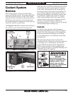
Note: Before adjusting the tailstock gib, loosen
the clamping hex bolts underneath both ends
of the tailstock (see Figure 122) to release the
clamping pressure between the upper and lower
castings. Test the gib adjustment by using the
offset adjustment screws. When you are satisfied
with the setting, retighten the clamping hex
bolts.
Figure 121. Carriage lock clamp.
Carriage
Lock
Clamp
Figures 118–122 show the location of the
adjustment screws for each gib on this machine.
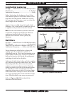
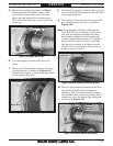
Figure 120. Front saddle gib adjustment screw.
Gib Adjustment
Screw (1 of 2)
Figure 119. One of two rear saddle gib adjustment
screws.
Saddle Rear
Gib Adjustment
Screw (1 of 2)
Figure 122. Tailstock gib adjustment controls.
Gib Adjustment
Screw (1 of 2)
Clamping Hex
Bolt (1 of 2)
Offset Adjustment
Screw (1 of 2)