


ASSEMBLY INSTRUCTIONS/OPERATION
SFCS-16 OPERATION AND PARTS MANUAL REV #3 (02/23/06) PAGE 11
Assembly
The STOW SFCS16 FLOOR COVERING SCRAPER
is shipped from the factory secured on a specially
designed wooden pallet and protected from external
damage by a corrugated carton or wood crate. If
shipped with a corrugated carton, the Surface Grinder
is secured to the pallet with wood support strips.
Remove the carton or crate immediately upon receipt
using suitable tools to remove the nails.
REMOVING THE FLOOR COVERING SCRAPER
FROM THE PALLET.
Tools Required:
1 each, cutting type pliers.
1 each, claw hammer or a hammer and an appropriate
pry bar.
Remove the corrugated carton which is fastened to the
pallet. The FLOOR COVERING SCRAPER is secured
to the pallet with banding. Using the pliers, cut and
remove the banding. The FLOOR COVERING
SCRAPER can then be removed from the pallet.
WEAR SAFETY GLASSES AND OTHER
APPROPRIATE SAFETY APPAREL WHEN
CUTTING THE BANDING AND/OR REMOVING THE
CORRUGATED/WOOD SHIPPING CRATE.
Included in the shipment should be the following:
1 each, FLOOR COVERING SCRAPER main frame
assembly.
1 each, extension cord with integral GFI.
1 each, adjustable section of the operator handle.
1 each, pack of standard blades.
The FLOOR COVERING SCRAPER is shipped from
the factory completely assembled with the exception
of the adjustable section of the operator handle. If
ordered with the Surface Grinder, optional blades and
accessories can be shipped separately or included in
the shipping container.
Visually inspect the shipment for freight damage
and/or missing parts. If shipping damage is evident,
contact the delivering carrier immediately to arrange
for an inspection of the damage by its claims
representative. Federal law requires that a claim be
filed within a specific time period. If missing parts are
detected, notify your dealer or the Customer Service
Department who will assist you in obtaining them.
Check all fasteners for proper security. Consult a
fastener torque chart for the proper torque value if any
fastener is found to require retorquing.
INSTALLATION OF THE ADJUSTABLE SECTION
OF THE OPERATOR HANDLE.
The installation of the adjustable section of the
operator will require a level working surface of
sufficient size and appropriate height.
1) The FLOOR COVERING SCRAPER incorporates
an operator handle design that folds for transport and
storage. The handle is secured to the main frame at
two locations; a pivoting (fixed) location secured by
Allen head type capscrews and a retaining (locking)
location secured by removeable, ball-detent type pins.
The pins are secured to the main frame by lanyards.
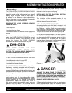
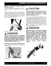
2) To place the operator handle in the work position,
move the handle upright so that the ball-detent pins
can be inserted through the operator handle and main
frame. Determine the ball-detent pins are properly
inserted through the operator handle and main frame
to fully expose the ball detent. FIGURE 1.
FIGURE 1
THE BALL DETENT MUST BE FULLY EXPOSED
AGAINST THE MAIN FRAME TO PROVIDE THE
PROPER PIN RETAINING FORCE. AN IMPROPER
PIN RETAINING CONFIGURATION CAN RESULT IN
UNEXPECTED OPERATOR HANDLE MOVEMENT.
THIS OCCURRENCE CAN RESULT IN PROPERTY
DAMAGE AND/OR PERSONAL INJURY.
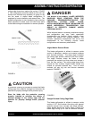
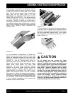
3) Remove the threaded knobs from the fixed section
of the operator handle. Install the adjustable section
into the fixed section with the handle grips facing
DANGER
DANGER