


ASSEMBLY INSTRUCTIONS/OPERATION
SFCS-16 OPERATION AND PARTS MANUAL REV #3 (02/23/06) PAGE 17
CAUTION
Do not substitute a different fastener type for the
button head capscrew configuration. The button
head configuration was chosen for operational
considerations. The use of another fastener types
can increase the potential for property damage
and/or personal injury.
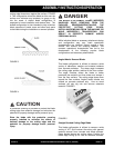
DANGER
BLADES ARE EXTREMELY SHARP. CONTACT
WITH THE BLADE CAN RESULT IN PROPERTY
DAMAGE AND/OR PERSONAL INJURY. BLADES
ARE PROVIDED WITH A PROTECTIVE COVER
OVER THE CUTTING EDGE. EXERCISE EXTREME
CAUTION WHEN REMOVING AND/OR
REINSTALLING THE PROTECTIVE COVER. STORE
THE BLADE WITH THE PROTECTIVE COVER
PROPERLY INSTALLED TO MINIMIZE THE
POTENTIAL FOR BLADE DAMAGE AND/OR
PERSONAL INJURY.
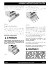
8) Return the FLOOR COVERING SCRAPER to its
normal operating position.
9) Determine that the ON/OFF switch located on the
operator handle is in the OFF position. If the FLOOR
COVERING SCRAPER is to be used immediately,
then reconnect the extension cord or FLOOR
COVERING SCRAPER to the power source.
DANGER
UNEXPECTED MACHINE START UP CAN RESULT
IN PROPERTY DAMAGE AND/OR PERSONAL
INJURY.
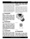
REMOVING THE BLADE OR CERAMIC TILE
RIPPER ATTACHMENT FROM THE FLOOR
COVERING SCRAPER.
Tools Required: 1 each, 5/32 inch T-handled Allen
wrench provided with the machine.
DANGER
WHEN INSTALLING OR REMOVING A BLADE OR
THE CERAMIC TILE RIPPER ATTACHMENT
TO/FROM THE FLOOR COVERING SCRAPER,
ALWAYS WEAR THE APPROPRIATE SAFETY
EYEWEAR, GLOVES, LEATHER SHOES AND
LONG PANTS TO MAXIMIZE PERSONAL
PROTECTION FROM THE SHARP EDGE(S).
IMPROPER CONTACT WITH A SHARP EDGE CAN
RESULT IN PROPERTY DAMAGE AND/OR
PERSONAL INJURY.
1) Properly disconnect the extension cord or the
FLOOR COVERING SCRAPER from the power
source.
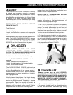
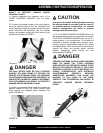
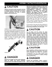
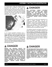
2) To place the operator handle in the work position,
move the handle upright so that the ball-detent pins
can be inserted through the operator handle and main
frame. Determine the ball-detent pins are inserted
through the operator handle and main frame to fully
expose the ball detent. FIGURE 15
FIGURE 15
DANGER
THE BALL DETENT MUST BE FULLY EXPOSED
AGAINST THE MAIN FRAME TO PROVIDE THE
PROPER PIN RETAINING FORCE. AN IMPROPER
PIN RETAINING CONFIGURATION CAN RESULT IN
UNEXPECTED OPERATOR HANDLE MOVEMENT.
THIS OCCURRENCE CAN RESULT IN PROPERTY
DAMAGE AND/OR PERSONAL INJURY.
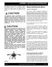
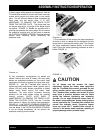
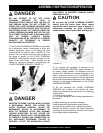
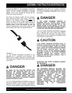
3) Loosen the threaded handle knobs and extend the
operator handle out until the internal handle stops
thrust against the treaded studs. Retighten the knobs.
FIGURE 16.