


ASSEMBLY INSTRUCTIONS/OPERATION
SFCS-16 OPERATION AND PARTS MANUAL REV #3 (02/23/06) PAGE 12
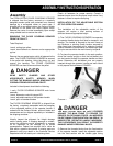
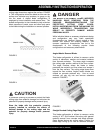
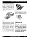
backwards toward the operator. FIGURE 2. Position
the adjustable section at a comfortable height.
Reinstall the threaded knobs and tighten until the
studs trust up tight against the adjustable handle
section.
The ergonomic design considerations of the
adjustable section of the operator handle will only
function if the handle grips are installed facing
backwards (toward) the operator. Installing the
adjustable section of the operator handle with the
handle grips facing forward (away) from the
operator will decrease machine control and
productivity.
INSTALLING THE ADJUSTABLE SECTION OF THE
OPERATOR HANDLE WITH THE HANDLE GRIPS
FACING FORWARD (AWAY) FROM THE
OPERATOR WILL NOT ALLOW THE THREADED
STUDS TO PROPERLY LOCATE WITHIN THE
SLOTS OF THE ADJUSTABLE HANDLE. THE SLOT
ENDS FORM INTEGRAL STOPS FOR THE
THREADED STUDS TO THRUST AGAINST. A
PROPER STUD/SLOT CONFIGURATION WILL
PREVENT THE ADJUSTABLE HANDLE FROM
INADVERTENTLY SEPARATING FROM THE FIXED
SECTION WHEN TRAVERSING AN INCLINE SUCH
AS A STAIRWAY. INADVERTENT SEPARATION OF
THE ADJUSTABLE HANDLE SECTION CAN
RESULT IN PROPERTY DAMAGE AND/OR
PERSONAL INJURY.
Improper knob tension and/or improperly securing
the operator handle to the main frame can result in
an unstable platform configuration. An unstable
platform configuration can result in property
damage and/or personal injury.
FIGURE 2
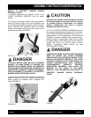
Before Starting the Motor
THEORY OF OPERATION.
The SFCS16 FLOOR COVERING SCRAPER is
designed to operate on the principle of various blades
and/or attachments oscillating with a random orbital
movement to remove a wide variety of covering
materials from work surfaces. Various types of multi-
accessory blades and/or accessory attachments are
secured to the exciter plate located on the bottom of
the machine. The specific type of blade and/or
accessory attachment utilized directly affects the type
of material removed, the material removal rate and the
resulting smoothness of the work surface.
The coverings removal process is directly controlled
by these conditions:
1) The use of a suitable mechanism (blade or
accessory attachment) of proper design and
configuration to scrape against the work surface and
remove material while delivering an acceptable
service life.
2) Sufficient static weight supporting the blade or
accessory attachment to allow it to effectively
penetrate and remove the covering material.
3) Adequate force exerted against the FLOOR
COVERING SCRAPER by the operator that pushes
the blade or accessory attachment against the
covering material to deliver acceptable productivity
rates.
4) Since no two covering materials are exactly alike,
no two covering materials can be removed by the
exact same method. The nature of the covering
removal process, along with operator experience, skill
and common sense, would suggest that efficient and
productive material removal is a matter of trial and
error. Combinations of blade or accessory attachment
type, jobsite conditions, and feed rates are direct
factors that will also determine the overall success of
the job application.
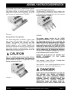
BLADE CONFIGURATIONS, ACCESSORY
ATTACHMENTS AND APPLICATIONS.
FLOOR COVERING SCRAPER blades are fabricated
from high carbon steel, precision machined and heat
treated for extended service life. Blades are marked to
depict use on either concrete or wood surfaces. When
utilized on concrete, the cutting edge is positioned
facing up. FIGURE 3. On wood flooring surfaces, the
CAUTION
CAUTION