


STUDER Innotec Xtender
Installation and operating Instructions Xtender V1.3 Page 18
{1140}
{1156}
{1138}
{1159}
a
d
e
28
29
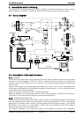
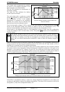
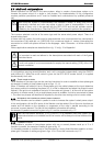
ACin=OK
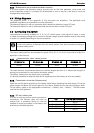
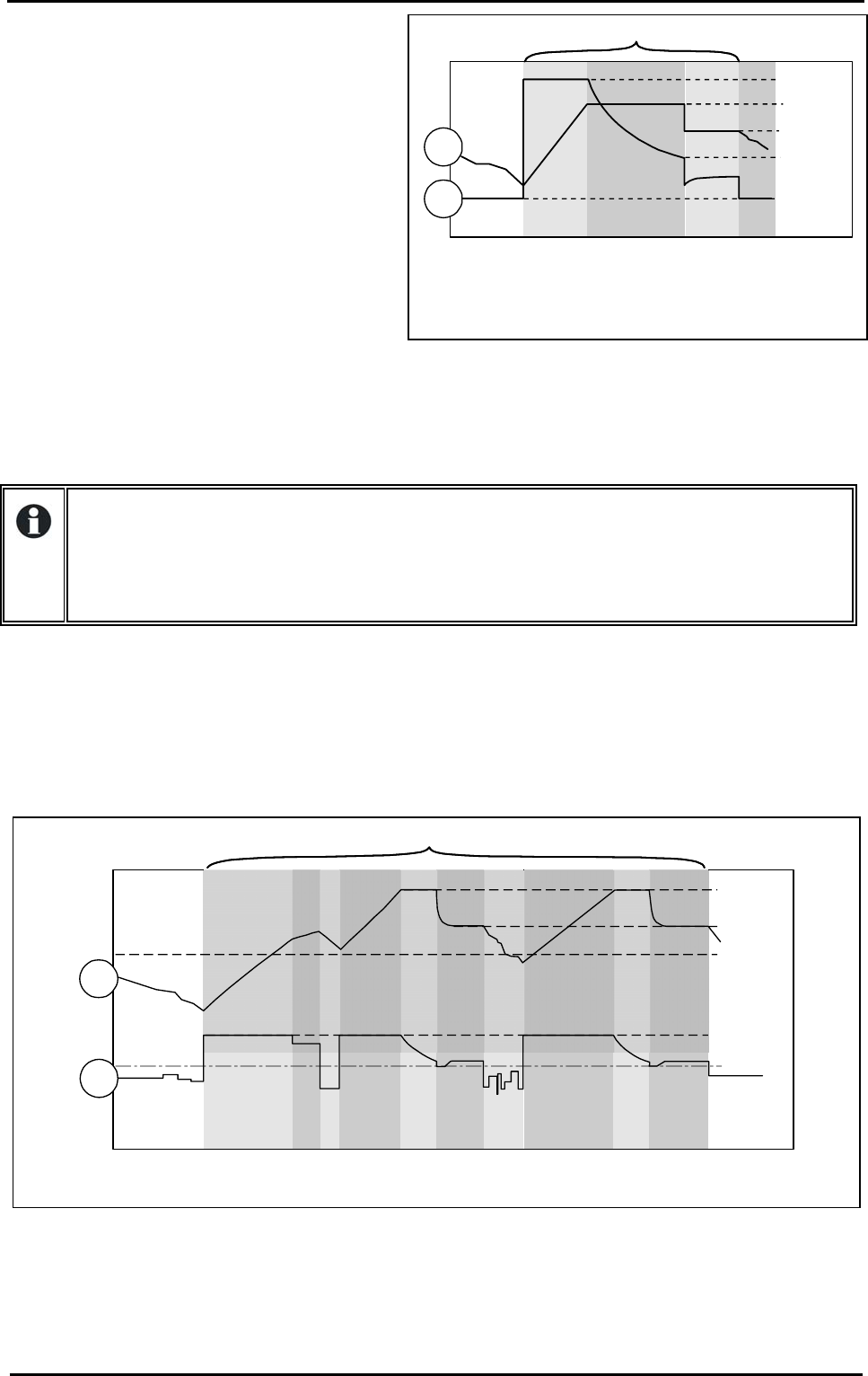
Cycle de charge simplifié, sans limitation de
courant d'entrée
The charge cycle, programmed by default,
as shown in the example described in the
figure opposite, runs automatically.
The line (28) indicates the development of
the battery voltage.
The lower line (29) indicates the battery
current (input and output).
The cycle starts with a continuous current
charge (a) adjusted by default according to
the configuration {1138}. If the ambient
temperature is increased or the ventilation
blocked, the current may be reduced and
become lower than the selected current.
Once the absorption voltage {1156) is reached, the cycle passes to voltage adjustment mode (d),
known as the absorption phase, the duration of which is set by the configuration {1157}. The
minimum interval between two absorption cycles is limited by the configuration {1161).
At the expiry of the absorption time, or if the absorption current is lower than the configuration
{1159}, the voltage is set to a lower value {1140}. This phase (e) is known as the maintenance or
“floating” phase.
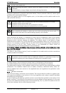
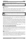
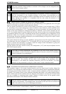
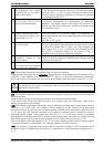
Given the limiting function for the input current (see the following p. 19), it is perfectly normal for the
charge current to be lower than the selected current if the limit of the AC input current {1107} is
reached (b). In this event the AC IN indicator (45) flashes.
If the “smart boost” function is activated {1126} and the power required by the consumer exceeds
the power of the source, the battery will be discharged (c) despite the presence of the grid or the
generator. In this case the LED “charge” (4) goes out. The consumers must ensure that they have
average consumption that is less than the power of the source (generator or public grid) in order to
avoid a complete discharge of the battery. These situations are set out in the figure below.
If the BTS-01 temperature sensor is used, the voltage adjustment thresholds for the battery are
corrected in real time by means of the battery temperature. The value of this correction is set by the
configuration {1139} in the configuration table p. 34.
If the battery voltage is lower than the critical disconnection threshold {1488} operation of
the charger will be automatically prevented. Only the transfer relay is authorised to operate
in this case. The battery must then be recharged by an external source up to a voltage
higher than the critical disconnection threshold in order to allow the Xtender charger to
operate.
ACin=OK
abcadec
ade
{1156}
{1140}
In
0
Out
{1143}
{1138}
28
29
Fig 3a
Charge cycle example with input current limitation and "smart boost”