


STUDER Innotec Xtender
Installation and operating Instructions Xtender V1.3 Page 7
3.5 Fastening
The Xtender is a heavy unit and must be mounted to a wall designed to bear such a load.
A simple wooden panel is insufficient.
The Xtender must be installed vertically with sufficient space around it to guarantee adequate
ventilation of the device (see figs. 2a and 2b).
If the Xtender is installed in a closed cabinet this must have sufficient ventilation to guarantee an
ambient temperature that conforms to the operation of the Xtender.
Firstly, fit the mounting bracket (18) supplied with the device, using 2 Ø <6-8 mm> screws**.
Then hang the Xtender on the bracket. Fasten the unit permanently using 2 Ø <6-8 mm> screws**
on to the two notches located at the underside of the case.
**: These items are not delivered with the device.
It is imperative to ensure complete and safe fastening of the device. A device that is simply
hung may detach and cause severe damage.
In motor vehicles or when the support may be subject to strong vibrations, the Xtender must be
mounted on anti-vibration supports.
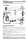
3.6 Connections
3.6.1
G
ENERAL RECOMMENDATIONS
The Xtender falls within protection class I (has a PE connection terminal). It is vital that a protective
earth is connected to the AC IN and/or AC OUT PE terminals. An additional protective earth is
located between the two fastening screws at the bottom of the unit (fig. 2b-(17)).
In all cases, the PE conductor for the equipment must at least be connected to the PE for
all equipment in protection class I upstream and downstream of the Xtender (equipotential
bonding). It is imperative that the legislation in force for the application concerned be
adhered to.
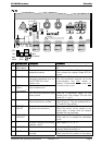
Tighten of the input (13) and output (14) terminals by means of a no. 3 screwdriver and those for the
“REMOTE ON/OFF” (7) and “AUX.CONTAC” (8) by means of a no. 1 screwdriver.
The cable sections of these terminals must conform to local regulations.
All connection cables as well as the battery cables must be mounted using cable restraints in order
to avoid any traction on the connection.
Battery cables must also be as short as possible and the section must conform with the applicable
regulations and standards. Sufficiently tighten the clamps on the “battery” inputs (fig. 4a (11) and
(12)).
3.6.2
D
EVICE CONNECTION COMPARTMENT
The unit’s connection compartment must remain permanently closed when in operation. It
is imperative to close the protection cap on the connection terminals after each intervention
in the device.
After opening, check that all
sources of AC and DC voltage (batteries) have been
disconnected or put out of service.