


STUDER Innotec Xtender
Installation and operating Instructions Xtender V1.3 Page 25
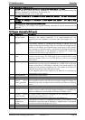
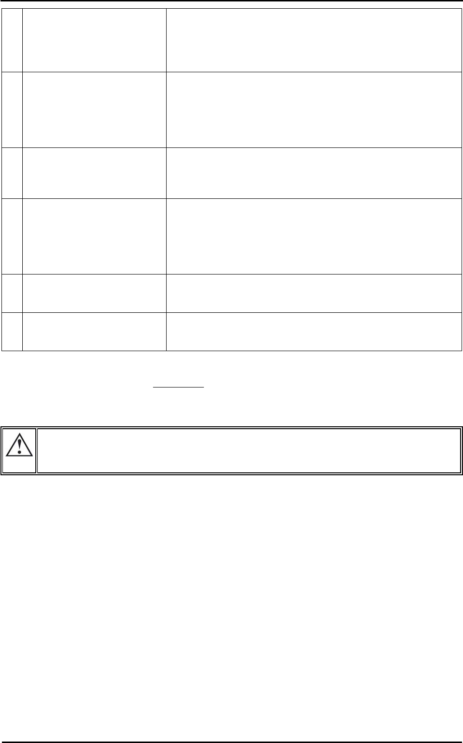
2x Stoppage due to overload in
the equipment, due to either
a short-circuit or too high a
load for the inverter.
In this event the equipment will make several attempts restart
{1133} every few seconds and will stop if the overload remains
(see chap. 6.2.9 – p. 20). It is vital to eliminate the cause of the
overload without restarting. Restarting is carried out manually
by pressing the button (41).
3x Decrease in the rated output
of the device due to a too
high internal temperature.
This may be due to too great a load for the device, at too high
an ambient temperature or counteracted or obstructed
ventilation. The power output of the device will therefore be
limited to around 50% of the Pnom. including in charger mode
or smart boost mode.
4x Battery voltage higher than
the maximum limit set by the
configuration {1121}.
Check the cause of this excess voltage. The equipment will
restart automatically when the voltage falls below the threshold
value {1122}.
see chap. 6.2.9 – p. 20
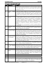
5x No transfer. Insufficient power
from the source
In this case, the Xtender remains in operation in inverter mode
until the output power decrease below the input limit and does
not allow the transfer relay to close. You must increase the
input current limit {1107}, or authorise the exceeding of this
limit {1436} or authorise backup on the source {1126}, or
disconnect some consumers (decrease of loads).
6x Startup prevented due to
unwanted voltage at the
device output.
Voltage is present at the device output. Check your cabling:
correct the fault and start the installation again using a manual
control on the button (41).
7x Indicates missing voltage on
one of the units of the system
in a multi-unit configuration.
Check the input protection devices (H) for all the system units.
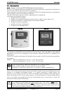
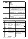
(43) This indicator is glowing continuously when the device is working.
It flashes when the equipment is temporarily
stopped due to a fault displayed by the indicator (42) or
a ON/OFF control cabled at the ”Remote ON/OFF” input (7), or when the equipment is intentionally
put to idle mode by the master unit in a multi-inverter parallel system (see chap. chap.6.3.2 - p. 22).
The equipment will restart automatically when the conditions that led to the temporary
stoppage have gone away.
(44) This indicator is glowing continuously when the charger is working and has not yet reached his
absorption phase.
It flashes twice during the absorption phase and once during the floating phase.
If the smart boost mode has been activated, this indicator goes out temporarily when source
backup is required by users (loads).
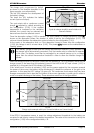
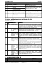
(45) This indicator is glowing continuously when a n alternative voltage with correct values, either in
frequency {1112-1505-1506}, or in voltage {1199} is present at the AC IN input of the device and
the current limit set by the user has not been reached. It flashes when the current limit at the input
{1107} set by the user has been reached. In this case the charger current is reduced in order to
guarantee priority supply to the users (see chap. 6.2.5 p. 19). If the input current is exceeded
nevertheless, the Xtender goes back to inverter mode (transfer relay open) and the indicator (42) will
keep flashing as long as the user current exceeds the limit value of the input current {1107}.
If the smart boost mode (see chapter 6.2.6 – p.19) is used and the inverter is part of the user supply
– therefore the battery is discharged – the “charge” indicator (44) will be glowing.
(46) This indicator is glowing continuously when an alternative voltage of 230V is present at the
equipment output. It flashes when the device is in “load search” mode according to chapter 6.2.2 –
p. 16.