


STUDER Innotec Xtender
Installation and operating Instructions Xtender V1.3 Page 23
6.4 Accessories
6.4.1
C
ONTROL CENTRE AND
RCC-02/03
(
REMOTE CONTROL
)
DISPLAY
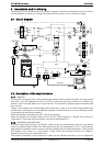
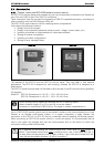
An RCC-02/03 remote display and programming unit can be optionally connected to the Xtender via
one of the two RJ45-8-type “Com. Bus” (3) connectors.
These connectors may only be used for connecting a CAN-ST compatible accessory, excluding any
other connection such as LAN, Ethernet, ISDN, etc.
The RCC-02/03 control centre is vital for modifying device configurations.
It also allows the following functions:
• Display of function synopsis
• Display of the measured operational values (current / voltage / power output, etc.)
• Updating of software or implementation of customised software
• Storage of inverter configuration
• Updating of inverter configurations
• Storage of error message history
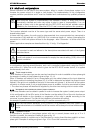
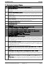
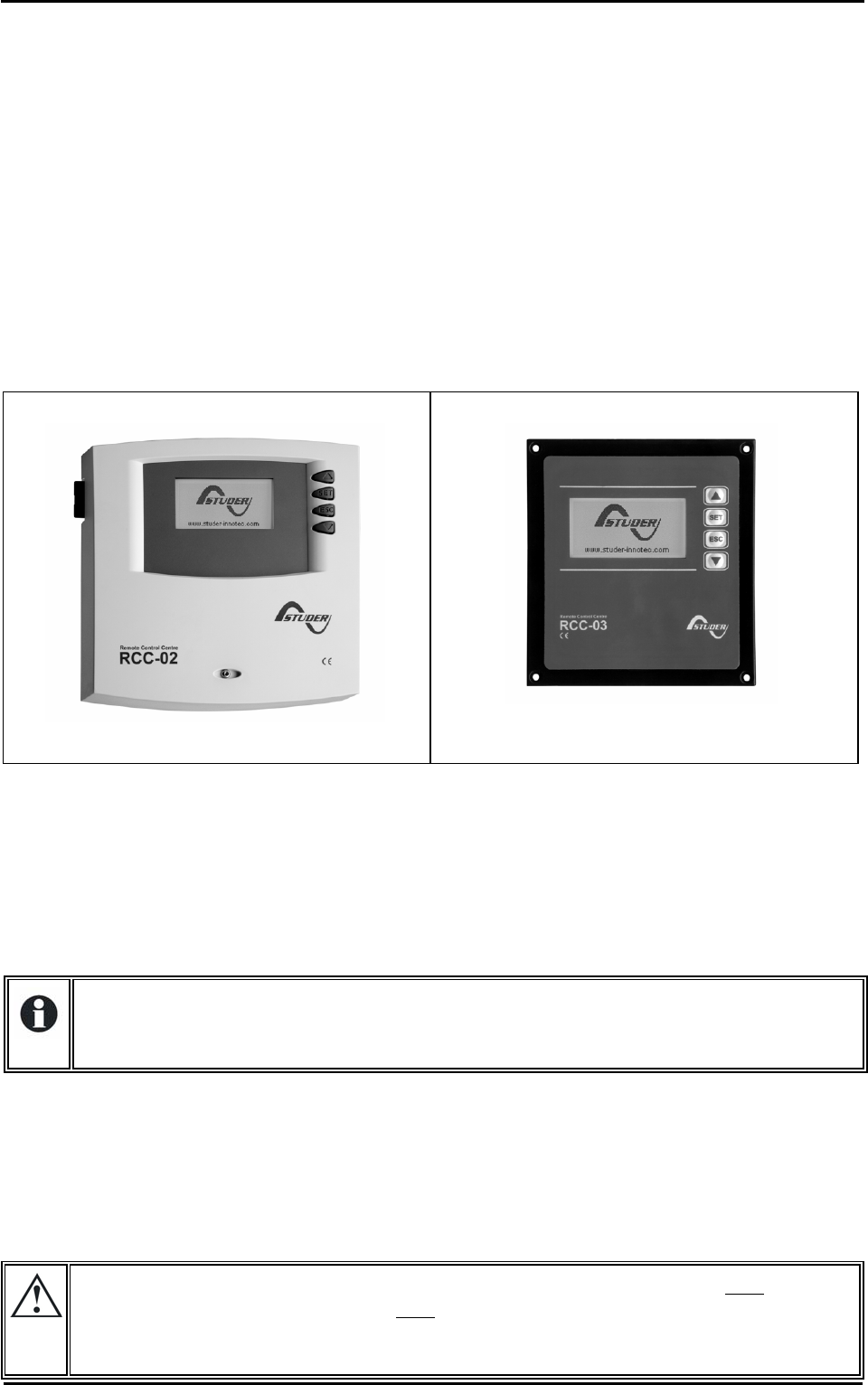
RCC-02
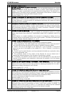
RCC-03
The features of the RCC-02 and the RCC-03 are the same. They only differ in their external
appearance. The RCC-02 is designed for wall mounting, whereas the RCC-03 is designed as a
board device.
The RCC-03 model must be taken off the table to allow access to the SD card slot (during updating,
for example).
Model N°: RCC-02: Dimensions: H x W x D / / 170 x 168 x 43.5mm
RCC-03: Dimensions: H x W x D / / 130 x 120 x 42.2mm
The two remote control models are delivered with a 2 m cable by default.
Cables of specific lengths (5 m, 20 m and 50 m) can be ordered.
The article no. is as follows: CAB-RJ45-xx. The length in metres is specified as xx
Up to 3 RCC-02/03 remote controls can be connected in series on the communication bus of one
Xtender or an Xtender multi-inverter system. In a system comprising a single Xtender, the
connection of the RCC-02 or RCC-03 may be conducted without stopping the Xtender (warm).
When connecting an RCC-02/03 remote control in a multi-unit system, it is recommended that all
units in the system be stopped and that the communication bus on the device on which the
connection is being made be terminated.
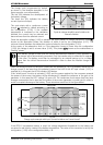
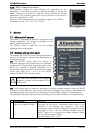
The 2 switches for terminating the communication bus, “Com. Bus" (4) both
remain in
position T (terminated) except when both
connectors are in use. In this case, and only in
this case, both must be placed in the O (open) position. If one of the two connectors is not
in use, the two termination switches (14) will be in position T.