


STUDER Innotec Xtender
Installation and operating Instructions Xtender V1.3 Page 29
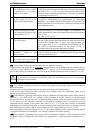
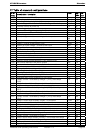
Fig. Description and comment
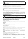
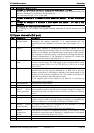
16 Example of cabling of 9 Xtenders in three-phase and parallel – AC part
Special feature: In fixed high power installations, it is advised that a shared neutral be
retained, distributed to all parties in the grid (see (C))
The comments for figs. 12 to 15 are valid.
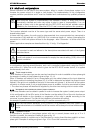
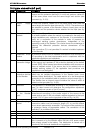
17 Example of cabling of 9 Xtenders in three-phase and parallel – DC part (distribution
bar)
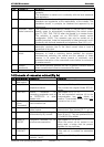
18 Example of cabling of 9 Xtenders in three-phase and parallel – DC part in star
formation
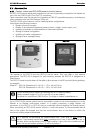
19 Connection of remote controls RCC-02/03
At a Xtender or at a system with several Xtender maximally 3 remote controls can be
attached.
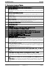
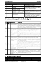
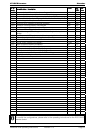
12 Figure element's (DC part)
Elem. Description Comment
a RCC-02/03
remote control
This device allows complete configuration of the installation as well as
displaying the system behaviour. It is recommended but not
necessary for the installation to function well. See chapter 6.4.1 – p.
23.
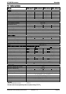
b Battery The battery capacity is constituted according to figures 5a to 6d
based on the required voltage. Note: It is vital that the voltage and the
polarity of the battery be checked before connecting to the inverter.
An overload or incorrect polarity could seriously damage the Xtender.
Correct dimensioning of the batteries is essential for trouble free
operation of the system. See chapter 4.3.1 – p. 11.
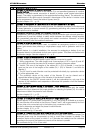
e Communications
cable
Communications cable. Only an original cable supplied by Studer
Innotec may be used. The total length of the communications cable
must not exceed 100 m for 3 x RCC-02/03 or 300 m for a single
RCC-02/03.
f Protection devices A fuse-type device, thermal circuit breaker or magnetic-thermal circuit
breaker (see fig. 8a) must be installed on at least one of the two
battery conductors. It will ideally be placed on the positive pole of the
battery and as close as possible to this. The calibre of the device is
selected according to the cable section used.
If the negative pole of the battery is not earthed, it must also be
protected by such a device.
h Distribution bar Positive pole of the battery
j Distribution bar Negative pole of the battery
k Wind-powered
or/and micro-
hxdro generator
One or more wind-powered generators or/and micro-hydro with their
own regulation system may be used to directly charge the battery. Its
dimensioning does not depend on the Xtender and does not interfere
with it.
L
m Solar generator One or more solar-powered generators with their own regulation
system may be used to directly charge the battery. Its dimensioning
does not depend on the Xtender and does not interfere with it.
r Remote control
via dry contact
A control device may be connected to the terminals (7) of the
Xtender. See chapter 6.2.12 – p. 21.
The length of the connection cable must not exceed 5 m.
t BTS-01
temperature
sensor
The sensor is placed in immediate proximity to the battery. If the
installation comprises several Xtenders, a single sensor is connected
to one of the units. See chap. 6.4.2 p.24