


STUDER Innotec Xtender
Installation and operating Instructions Xtender V1.3 Page 32
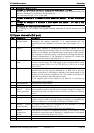
Pos. Denomination Description Comment
10 L1/L2/L3 Phase selection jumpers. See chapter 6.3.1. – p.22.
Jumper default at position L1
11 +BAT Positive pole battery connection
terminals
12 -BAT Negative pole battery
connection terminals
Carefully read chapter 4.5 – p.12
Take care with the polarity of the battery
and when tightening the clamp.
13 AC Input Connection terminals for the
alternative power supply
(generator or public network)
See chapter 4.5.7 - p. 14.
Note: It is imperative that the PE terminal
be connected.
14 AC Output Connection terminals for the
device output.
See chapter 4.5.6 - p. 14.
Note: Increased voltages may appear on
the terminals, even in the absence of
voltage at the input of the inverter.
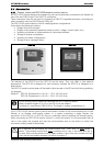
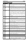
15 Control and display parts for the Xtender (fig. 4b)
See chapter 7.2 - p. 24.
Pos.
Denomin
ation
Description Comments
41
ON/OFF
ON/OFF button The ON/OFF button allows the start up or complete stoppage
of the system such as it has been programmed. When there
are several units in the same system, each unit must be
started up or stopped individually using this button.
42 OFF Light indicator
for stoppage of
the unit
When the light indicator flashes it indicates the cause of the
stoppage of the unit, its imminent stoppage or the limitation of
its rated power output according to chapter 7.2 - p.24.
43 ON Light indicator
showing that the
equipment is in
operation
This indicator is glowing continuously when the device is
working. It flashes when the equipment is at a temporary
stop. Note: The equipment will restart automatically when the
conditions that led to the temporary stoppage have gone
away.
44 Charge Light indicator
showing that the
battery is being
charged
This indicator is glowing continuously when the charger is in
operation and has not yet reached the absorption phase.
It flashes twice during the absorption phase and once during
the maintenance phase.
If smart boost mode has been activated it is possible that this
indicator will go out temporarily when source backup is
required by users. (See chapter 6.2.6 - p. 19)
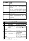
45 AC in Light indicator
showing the
presence of
correct and
synchronised
input voltage
This indicator is glowing continuously when an alternative
voltage with correct values is present at the AC IN input (13)
of the device and the current limit {1107) set by the user has
not been reached. It flashes when this limit is reached (see
chapter 6.2.5 – p. 19).
46 AC out Light indicator
showing the
presence of a
voltage at the
output
This indicator is glowing continuously when an alternative
voltage of 230V is present at the device output. It flashes
when the device is in “load search” mode due to the absence
of users. (See chapter 6.2.3 – p. 16)
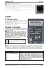
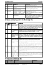
16 Type plate elements (fig. 1b)
Pos. Denomination Description Comments
31 Model Model
32 Pnom/P30 Rated power output / power for 30 minutes