


STUDER Innotec Xtender
Installation and operating Instructions Xtender V1.3 Page 27
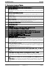
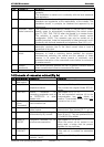
11 Comments of annexes’ figures
Fig. Description and comment
1a
Dimensioning table for the downstream protection device (F). See chap. 4.5.6 – p.14.
1b
Type plate and series no.
See chapter 16 - p. 32.
The intactness of this label is vital for any possible warranty claims. It must not be altered
or removed.
2a
Dimensions and fastening the device
The support (wall) must be appropriate for supporting the increased weight of the device
without any risk.
2b
Installation distance
Insufficient distance or an increased ambient temperature can reduce the rated power
output of the device.
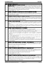
3a
Battery charge cycle
Charge cycles that are more complex than those described in chap. 6.2.4 – p. 17 of this
manual may be programmed via the RCC-02/03 remote control
.
3b
Simplified battery charge cycle:
See chapter 6.2.4 - p. 17.
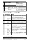
4a
Device connection box
See chapter 3.6.2 – p. 7.
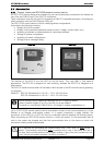
4b Control table See chapter 7.2-p. 24.
5a
12 V battery: connection in series and in parallel / series for 2 V cell
5b 12 V battery: connection of 12 V battery in parallel
5c 24 V battery: connection in series and in parallel / series for 2 V cell
5d 24 V battery: connection in series and in parallel / series for 12 V battery block
6a 48 V battery: connection in series and in parallel / series for 12 V battery block
6b 48 V battery: connection in series for 12 V battery block
6c 48V battery: Series connection of 2V cell
6d 48 V battery: connection in parallel / series for 2 V cell
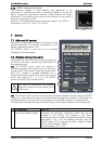
7 Xtender circuit diagram
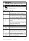
8a Single-phase installation (AC and DC part)
This example illustrates the most routinely used installation, allowing the attainment of an
emergency system or a hybrid system (remote sites) ensuring the supply in single-phase
from a generator and/or the battery when the AC source is absent. See also chapter
4.1.1.1 / 4.1.2 – p. 9.
8b ON/OFF remote control variants
This example illustrates the various options for connecting the “REMOTE ON/OFF” input
(7), enabling the ON and OFF controls of the Xtender via a contact or a voltage source.
See also chap. 6.2.12 – p. 21.
The maximum length for this control should not exceed 5 m.
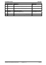
8c Installation with three-phrase source and secured single-phase output – AC and DC
part
In this example, the three-phase users will only be supplied when the generator or grid are
operating.
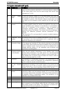
9a Fixed installation with plug connection to the single-phase source – AC part
Special feature: The connection of the neutral upstream and downstream of the Xtender
(C) is prohibited in this configuration (presence of a plug upstream). See also chapter 4.2.1
– p. 10.
9b Fixed single-phase installation with connection by plug to a three-phase source – AC
part
Special feature:
The connection of the neutral upstream and downstream of the 'Xtender
(C) is prohibited in this configuration (presence of a plug upstream). See also chapter 4.2.1
– p. 10.