


12
Drainage
Provide a large-capacity drain for
water vessel drain-down during
shutdown or repair. The evaporator
is provided with a drain connection.
All local and national codes apply.
The vent on the top of the
evaporator water box is provided to
prevent a vacuum, by allowing air
into the evaporator for complete
drainage.
Releasing the Nitrogen
Holding Charge
The nitrogen holding charge can be
released into the atmosphere.
ƽƽ CCAAUUTTIIOONN
When releasing nitrogen holding
charge, ventilate the room. Avoid
breathing in the nitrogen.
Water Connections (RTUB)
Thoroughly flush all water piping to
the unit before making the final
piping connections to the unit.
ƽƽ CCAAUUTTIIOONN
If using an acidic commercial
flushing solution, construct a
temporary bypass around the unit to
prevent damage to internal
components of the evaporator. To
avoid possible equipment damage,
do not use untreated or improperly
treated system water.
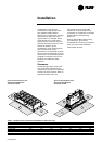
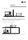
When making the water connections,
use flange connectors. Insulate all
piping to reduce temperature
increases and to prevent
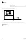
condensation. Figure 7 shows all the
piping systems for the evaporator
and its components. The
arrangement of the pipes and the
other components varies slightly
according to the positioning of the
connections and the water source.
ƽƽ CCAAUUTTIIOONN
The chilled water connections to the
evaporator are Victaulic connections.
Do not attempt to weld these
connections, because the heat
generated from welding can cause
microscopic and macroscopic
fractures on the cast- iron water
boxes that can lead to premature
failure of the water box.
A vent line is located on the top part
of the evaporator at the water return
piping end. Install additional vent
lines at the highest points in the
piping to vent the air present in the
chilled water circuit. Install
manometers to monitor the pressure
of chilled water entering and leaving
the evaporator.
ƽƽ CCAAUUTTIIOONN
To prevent damage to chilled-water
components, do not allow
evaporator pressure (maximum
working pressure) to exceed 10.5
bars.
Provide shutoff valves in lines to the
gauges, in order to isolate them from
the system when they are not in use.
Use rubber vibration eliminators to
prevent vibration transmission
through the water lines. If desired,
install thermometers in the lines to
monitor entering- and leaving-water
temperatures. Install a balancing
valve in the leaving-water line to
control water flow balance. Install
shutoff valves on both the entering-
and leaving-water lines so that the
evaporator can be isolated for
service. A pipe strainer must be
installed in the entering water line.
Failure to do so can allow
waterborne debris to enter the
evaporator.
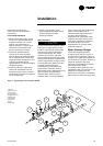
"Piping components" include all
devices and controls used to provide
proper water system operation and
unit operating safety. These
components and their general
locations are given in Figure 7.
Entering Chilled-Water Piping
• Air vents (to bleed air from system).
• Water pressure gauges with shutoff
valves.
• Vibration eliminators.
• Shutoff (isolation) valves.
• Thermometers (if desired).
• Clean out tees.
• Pipe strainer.
ƽƽ CCAAUUTTIIOONN
Install a strainer in the evaporator-
water inlet piping. Failure to do so
can result in evaporator tube
damage.
Leaving Chilled-Water Piping
• Air vents (to bleed air from system).
• Water pressure gauges with shutoff
valves.
• Vibration eliminators.
• Shutoff (isolation) valves.
• Thermometers (if desired).
• Clean out tees.
• Balancing valve.
• Flow Switch
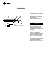
Evaporator Drain
A 3/4" drain connection is located
under the outlet end of the
evaporator water box. This may be
connected to a suitable drain to
permit evaporator drainage during
unit servicing. A shutoff valve must
be installed on the drain line.
Evaporator Flow Switch (accessory)
The chilled water flow is protected
by the UCM-CLD without the
assistance of a chilled water flow
switch. The flow switch is optional,
but if it is not installed, a signal must
be sent to the chiller to indicate the
water flow is established, for
example the auxiliary contacts of the
chilled water pump starter.
If additional protection of the chilled
water flow proves necessary,
connect a flow switch installed on
site, or a differential pressure switch
to control the system's water flow.
Connect the flow switch in series
with the auxiliary contacts of the
chilled water pump motor starter. A
special connector is supplied with
the unit, with the wiring diagrams.
Some piping and control schemes,
particularly those using a single
water pump for both chilled- water
and hot water, must be analyzed to
determine how and/or if a flow-
sensing device will provide the
desired operation.
Installation
RLC-SVX03A-E4