


25
Perform all maintenance procedures
and inspections at the recommended
intervals. This will prolong the life of
the chiller and minimize the
possibility of costly failures. After the
unit has been operating for
approximately 30 minutes and the
system has stabilized, check the
operating conditions and complete
the following procedures:
Weekly Maintenance
While the unit is running in stable
conditions:
1. Check the UCM pressure for
Evaporator, Condenser, and
Intermediate Oil.
2.Measure the subcooling entering
the EXV. The subcooling should
never be less than 2.2°C under any
circumstances.
ƽƽ CCAAUUTTIIOONN
Also check the rest of the system
operating conditions.
3. Inspect the entire system for
unusual conditions and inspect the
condenser coils for dirt and debris.
If the coils are dirty, refer to coil
cleaning.
Monthly Maintenance
1. Perform all weekly maintenance
procedures.
2. Record the system subcooling.
3. Record the system superheat.
4. Make any repairs necessary.
Annual Maintenance
1. Perform all weekly and monthly
procedures.
2. Check the oil sump oil level while
the unit is off.
Note: Routine changing of the oil is
not required. Use an oil analysis to
determine the condition of the oil.
3. Have a qualified laboratory
perform a compressor oil analysis
to determine system moisture
content and acid level. This
analysis is a valuable diagnostic
tool.
4. Contact a qualified service
organization to leak-test the chiller,
to check operating and safety
controls, and to inspect electrical
components for deficiencies.
5. Inspect all piping components for
leakage and damage. Clean out
any inline strainers.
6. Clean and repaint any areas that
show signs of corrosion.
7. Clean the condenser coils.
ƽƽ WWAARRNNIINNGG
Position all electrical disconnects in
the "Open" position and lock them
to prevent injury or death due to
electrical shock.
8. Check and tighten all electrical
connections as necessary.
Coil Maintenance
Because seacoast applications are
considered to be a "dirty"
environment for condenser coils, it is
logical that the coils will need to be
cleaned more often than a coil
located inland. Cleaning four times a
year may be required or even more if
conditions are very poor or if
corrosion damage begins to occur.
To clean the coils, use a soft brush
and a sprayer (garden pump-up
type). A high-quality detergent, such
as "Trane Coil Cleaner, CHM0021" is
recommended for both standard and
coils with aluminium coating.
Follow the directions included with
the detergent. The most effective
method of coil cleaning is to remove
the condenser end panels and clean
the coils from the inside out using
the sprayer.
ƽƽ CCAAUUTTIIOONN
If the detergent used is strongly
alkaline (pH greater than 8.5), an
inhibitor must be added.
Rinse the coil thoroughly after
cleaning. Failure to completely flush
the detergent from the coil can result
in accelerated coil corrosion. Blow
excess water from the coil using low-
pressure air. The water used to clean
the coils should always be clean,
fresh water (it should not be
brackish, or contain excessive
dissolved minerals, chlorine, or
water softener salts.)
Chemical Cleaning of the Evaporator
(RTUB)
The chilled water circuit is a closed
circuit, and therefore should not
accumulate scale or sludge. If the
chiller becomes obstructed, you can
attempt to unblock it by reversing
the water flow direction. If
unsuccessful after several attempts,
clean the evaporator chemically.
ƽƽ WWAARRNNIINNGG
Do not use an acid cleaning product
which might damage steel,
galvanized steel, polypropylene and
copper parts.
Contact a local water treatment
company advice on a suitable
chemical product for this unit. The
supplier of the cleaning product
must supply or approve:
• All devices used in the circuit
• The quantity of chemical product to
use
• The duration for which the chemical
product must circulate in the
evaporator
• Safety precautions and
recommendations for using and
handling the chemical product
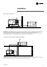
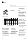
Replacing the Oil Filter
Note: Routine changing of the oil or
oil filter is not recommended. The oil
filter is oversized for this application
and should not require replacement.
The oil and filter should be replaced
only if analysis reveals that the oil is
contaminated. Oil type and system
capacities are shown in Table 1.
Pressure drop across the oil filter is
shown in Figure 15. Oil filter
pressure drop is the difference
between the two pressure-control
ports.
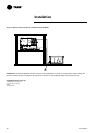
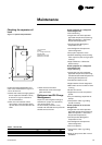
To change the oil filter in the unit,
refer to Figure 15 and follow the
steps listed.
Maintenance
RLC-SVX03A-E4