


28
Some symptoms of an oil under-
charged unit:
• Compressor rattle or grinding
sound
• Lower-than-normal pressure drop
through oil system
• Seized or Welded Compressors
• Low oil-sump level after normal
shutdown
• Lower-than-normal oil
concentrations in the evaporator
R134a Field-Charging
Procedure
Be certain that the electrical power to
the unit is disconnected before
performing this procedure.
ƽƽ WWAARRNNIINNGG
Position all electrical disconnects in
the "Open" position and lock them to
prevent injury or death due to
electrocution. Follow this procedure
when the unit is empty of all
refrigerant and under a vacuum.
ƽƽ CCAAUUTTIIOONN
Water must be flowing through the
evaporator during the entire
charging process to avoid freezing
and rupturing of the evaporator
tubes.
1. Find the weight of the amount of
charge given in Table 1.
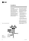
2. Attach the charging hose to the
evaporator service valve (3/8"
[9 mm] flare). Open the service
valve.
3. Add charge to the evaporator to
bring the total circuit charge up to
the level given in Table 1.
4. Close the service valve and
disconnect the charging hose.
Adding charge
This procedure should be followed
when adding charge to an
undercharged unit. When low charge
is indicated by low subcooling in the
liquid line, charge should be added
until sufficient subcooling is
achieved.
1. Attach the charging hose to the
evaporator service valve (3/8"
[9 mm] flare). Open the service
valve.
2. Add 4.5 kg of refrigerant (R134a)
charge.
3. Close the valve, remove the
charging hose and start the unit.
Monitor subcooling.
4. If subcooling is still insufficient,
return to step number 2.
Note: Proper subcooling can be
determined from run-log history,
service experience, or by contacting
Trane technical service. The service
tool may include a calculation
module that determines the proper
subcooling for any operating
condition (Trane Service only).
Charge Isolation in the high
or low side of the system
All the refrigerant may be trapped
into the high side (condenser) of the
unit for maintenance on the
compressor (or low side). With the
suction-line service valve option,
charge may also be isolated in the
evaporator for maintenance on the
compressor (or high side). It is much
more preferable to isolate the charge
in the evaporator, if this option is
available.
High side charge isolation procedure:
1. Make sure the circuit is off.
2. Shut the liquid-line service valve.
3. Shut the oil return-line service
valve.
4. Start the circuit with the service
tool in charge-isolation mode:
• All fans will turn on
• EXV will open 100%
• The oil return-line solenoid will
open
• The unit will start at minimum load
• The unit will run until it cuts out on
low pressure (~6 psia) [0.41 bar].
5. When the unit trips, the discharge
check valve and the oil-line shutoff
valve close.
6. Close the discharge isolation
valve.
7. Close the oil-line shutoff valve.
8. Remove the remainder of the
charge with the vacuum pump.
Recommendation: Do not pump
the remaining charge into the high
side. This may introduce non-
condensable gasses and other
contaminants into the unit.
9. The low side and the compressor
may be serviced at this time.
Returning the unit to running
condition:
1. Open all the valves.
2. Manually open EXV for 15 minutes
to allow the refrigerant to drain to
the evaporator by gravity.
3. Let the unit sit with heaters on to
drive refrigerant out of the oil and
warm up the compressor
bearings. Depending upon
ambient conditions, this may take
up to 24 hours.
4. After the oil level has returned to
normal, the unit can be put back
into operation.
Low-side charge-isolation procedure:
After normal shutdown, most of the
charge resides in the evaporator.
Running cold water through the
evaporator may also drive much of
the refrigerant to the evaporator.
1. Make sure the circuit is off.
2. Close the suction-line isolation
valve.
3. Close the oil return-line service
valve.
4. Close the liquid line service valve.
5. Manually open the EXV.
6. Use a liquid pump or vacuum
pump to move refrigerant from
the condenser to the evaporator.
The liquid pump will only be
effective if there is a lot of charge in
the condenser. It may be connected
to the condenser drain port on the
liquid-line isolation valve.
Note: if a pump is to be used,
connect it before closing this valve.
This port is only isolated when the
valve is backseated. If a vacuum
pump is used, then connect it to the
discharge-line service valve near the
oil separator. A vacuum pump will be
required for part of the procedure.
Maintenance
RLC-SVX03A-E4