


22
Operation
motor rotation requires confirmation
of the electrical phase sequence of
the power supply. The motor is
internally connected for clockwise
rotation with the incoming power
supply phased A-B-C.
When rotation is clockwise, the
phase sequence is usually called
"ABC;" when counterclockwise,
"CBA." This direction may be
reversed outside the alternator by
interchanging any two of the line
wires. It is this possible interchange
of wiring that makes a phase
sequence indicator necessary if the
operator is to quickly determine the
phase rotation of the motor.
1. Press the Stop key on the UCM-
CLD.
2. Open the electrical disconnect or
circuit protection switch that
provides line power to the line-
power terminal block(s) in the
starter panel (or to the unit-
mounted disconnect).
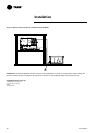
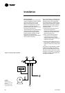
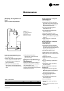
3. Connect the phase-sequence
indicator leads to the line power
terminal block as follows:
Phase Sequence Lead Terminal
Black (Phase A) L1
Red (Phase B) L2
Yellow (Phase C) L3
4. Turn power on by closing the unit
supply-power fused-disconnect
switch.
5. Read the phase sequence on the
indicator. The "ABC" LED on the
face of the phase indicator will
glow if the phase is "ABC."
ƽƽ WWAARRNNIINNGG
To prevent injury or death due to
electrocution, take extreme care
when performing service procedures
with electrical power energized.
6. If the "CBA" indicator glows
instead, open the unit main-power
disconnect and interchange two
line leads on the line-power
terminal block(s) (or the unit-
mounted disconnect). Close the
main-power disconnect and
recheck the phasing.
Do not interchange any load leads
that are from the unit contactors or
the motor terminals. Doing so may
damage the equipment.
7. Reopen the unit disconnect and
disconnect the phase-sequence
indicator.
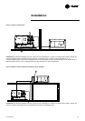
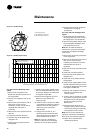
Water-System Flow Rates
Establish a balanced chilled-water
flow through the evaporator. The flow
rates should be between the
minimum and maximum values
given on the pressure-drop curves.
Water-System Pressure Drop
Measure the water-pressure drop
through the evaporator at the field-
installed pressure taps on the system
water piping. Use the same gauge for
each measurement. Do not include
valves, strainers, or fittings in the
pressure-drop readings.
Start-up Procedures
Daily Unit Start-up Procedure
When the verification operations
prior to start-up have been performed
(see previous sections), the unit is
ready to start.
• Press the Stop key on the UCM-CLD.
• If necessary, adjust the setpoint
values in the UCM-CLD reports
(refer to the UCM-CLD user guide).
• Close the fused disconnect switch
for the chilled water pumps and the
cooling water pumps.
• Energize the pumps to start the
water circulation.
• Check the service valves on the
discharge line, suction line, oil line
and liquid line for each circuit.
These valves must be open before
starting the compressors.
ƽƽ WWAARRNNIINNGG
To prevent compressor damage, do
not operate the unit until all
refrigerant and oil-line valves are
opened.
• Verify that the chilled water pump
runs for one minute after the chiller
is commanded to stop for normal
chilled water systems).
• Press the Auto key. If the chiller
control calls for cooling and all the
safety interlocks are closed, the unit
will start. The compressor(s) will
load and unload in response to the
temperature of the leaving chilled-
water temperature.
After the system has been operating
for approximately 30 minutes and
has become stabilized, complete the
start-up procedure as follows:
• Check the evaporator refrigerant
pressure and the condenser
refrigerant pressure in the
Refrigerant report of the UCM-CLD.
• Measure the system overheat.
• Measure the system subcooling.
A shortage of refrigerant is indicated
if the operating pressures and the
subcooling are low. If the operating
pressures, superheat, and
subcooling readings indicate a
refrigerant shortage, gas-charge
refrigerant into each circuit as
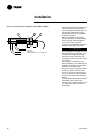
required. With the unit running, add
refrigerant vapor by connecting the
charging line to the suction service
valve and charging through the
backseat port until operating
conditions become normal.
ƽƽ WWAARRNNIINNGG
If both suction and discharge
pressures are low and subcooling is
normal, a problem other than
refrigerant shortage exists. Do not
add refrigerant, as this may result in
overcharging the circuit.
Only use the refrigerant specified on
the unit nameplate.
• If operating conditions indicate a
refrigerant overcharge, remove
refrigerant at the liquid line service
valve. Allow refrigerant to escape
slowly to minimize oil loss. Do not
discharge refrigerant into the
atmosphere.
ƽƽ WWAARRNNIINNGG
Do not allow refrigerant to directly
contact skin, or injury from frostbite
may result.
Overheating
Normal overheating for each circuit
is approximately 3-4°C at full
RLC-SVX03A-E4