


15
Installation
withstanding high temperatures
without degradation.
ƽƽ CCAAUUTTIIOONN
A defect in fixing or insulating the
condensation sensors may cause
incorrect adjustment and/or damage
to the compressor.
If the sensor cannot be mounted in
the place where the saturated gas
enters the sub-cooler, it must be
positioned on the sub-cooler side
and not on the condenser side. If the
condenser temperature cannot be
measured, it is preferable to
measure the liquid temperature
instead of the discharge
temperature.
ƽƽ CCAAUUTTIIOONN
To prevent interference, separate the
sensor cables from the power cables.
Electrical connections
performed by the installer
All wiring must comply with local
codes. Specific electrical schematics
and connection diagrams are
shipped with the unit.
ƽƽ CCAAUUTTIIOONN
To avoid corrosion and overheating
at terminal connections, use copper
conductors only. Failure to do so
may result in damage to the
equipment. Do not allow conduit to
interfere with other components,
structural members or equipment.
Control voltage (110 V) wiring in
conduit must be separate from
conduit carrying low voltage (<30 V)
wiring. To prevent control
malfunctions, do not run low voltage
wiring (<30 V) in conduit with
conductors carrying more than 30 V.
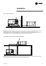
Connecting the RTUB with a remote
air-cooled condenser
The RTUB unit is shipped with a
holding nitrogen charge and a
separate oil charge. The RTCA
condenser is designed to operate
with the RTUB unit. To ensure
optimum operation and
performance, the RTUB must be
installed with the RTCA condenser. If
correctly, refer to the general
recommendations. Connect the
outside air sensor 5R3 to terminals 1
and 2 on terminal board 1. Connect
the condenser sensor 5R56-1 to
terminals 4 and 5 on terminal board
J4 on module A20-1. Connect the
condenser sensor 5R56-2 to
terminals 4 and 5 on terminal J4 on
module A20-2.
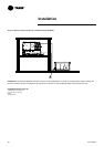
If the condenser is not an RTCA,
ambient temperature and condenser
temperature sensors must be
connected to the RTUB to monitor it.
The ambient temperature sensor
must be installed in a position which
represents most accurately the
condenser's surrounding
environment. It must not be exposed
to sunlight or precipitation. Ensure
that the sensor is not located in the
flow of recycled air from the
condenser discharge. The
condensation temperature sensors
must be installed on the refrigerant
piping at the place where it leaves
the condenser to enter the sub-
cooler. It is necessary to install a
condenser temperature sensor on
each refrigerant circuit. This sensor
must be fixed in compliance with the
method used to attach the bulb for a
thermostat expansion valve. This
sensor can be fixed outside the
piping if it is sufficiently insulated
with insulation capable of
convenient position. Plug the sensor
cable and the cable connected to the
control panel into the junction box.
The shielded cable can be cut to the
required length.
Note: To lengthen the sensor's power
cable, use 0.75 to 1.25 mm²
conductors, 600V. The cable used
between the junction box and the
control panel must either be shielded
or in a duct. If a shielded cable is
used, make sure it is not used with
other cables carrying 30 V or more.
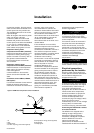
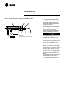
Evaporator leaving water
temperature sensor 5R51 (standard)
Install this temperature sensor in the
evaporator's leaving water piping
system. To install it correctly, refer to
the general recommendations.
Connect this sensor to terminals
X7-1 and X7-2.
Evaporator entering water
temperature sensor 5R52 (standard)
Install this sensor in the evaporator
water piping. To install it correctly,
refer to the general
recommendations. Connect this
sensor across terminals X6-1 and
X6-2.
Condenser sensors 5R56-1, 5R56-2,
5R3 (option)
If an RTCA condenser is used with an
RTUB, the sensors required are
installed on the RTCA. To install them
1
6
7
3
4
5
2
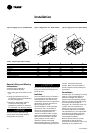
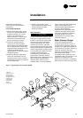
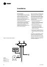
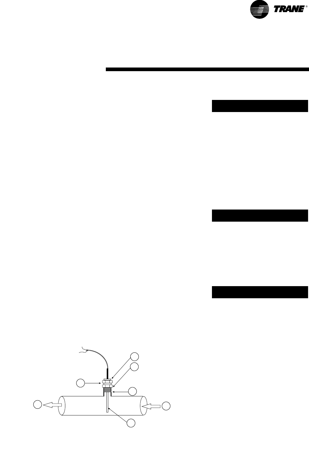
Figure 9: UCM water temperature sensor installation
1 In
2 Out
3 UCM sensor
4 ¼" NPT coupling (customer-supplied)
5 Compression fitting (Trane-supplied)
6 Fitting body
7 Clamping nut
RLC-SVX03A-E4