


13
Follow the manufacturer's
instructions for the installation
procedures.
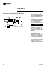
Flow Switch Installation
1. Mount the switch upright, with a
minimum of 5 pipe diameters of
straight horizontal run on each
side. Do not install close to
elbows, orifices, or valves. Note:
The arrow on the switch must
point in the direction of flow.
2. To prevent switch fluttering,
remove all air from the water
system. Note: The UCM-CLD waits
for six seconds after a “flow loss”
diagnosis before stopping the unit.
Contact a qualified service
representative if nuisance machine
shutdowns persist.
3. Adjust the switch to open when
water flow falls below nominal.
Evaporator data is given in Table 1.
Flow-switch contacts are closed on
proof of water flow.
4. Install a pipe strainer in the
entering evaporator-water line to
protect components from
waterborne debris.
Water Treatment
ƽƽ CCAAUUTTIIOONN
If calcium chloride is used for waste
treatment, an applicable corrosion
inhibitor must also be used. Failure
to do so may result in damage to
system components. Dirt, scale,
products of corrosion, and other
foreign material will adversely affect
heat transfer between the water and
system components. Foreign matter
in the chilled-water system can also
increase pressure drop and,
consequently, reduce water flow.
Proper water treatment must be
determined locally, depending on the
type of system and local water
characteristics. Neither salt nor
brackish water is recommended for
use in Trane units. Use of either will
lead to a shortened life to an
indeterminable degree. The Trane
Company encourages the
employment of a reputable water
treatment specialist, familiar with
local water conditions, to assist in
this determination and in the
establishment of a proper water-
treatment program.
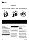
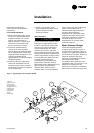
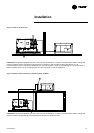
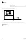
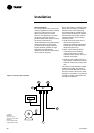
Water Pressure Gauges
Install field-supplied pressure
components as shown in Figure 7.
Locate pressure gauges or taps in a
straight run of pipe; avoid placement
near elbows, and so forth. Be sure to
install the gauges at the same
elevation on each shell if the shells
have opposite-end water
connections. Note: After the unit is
installed at a site, one vertical (or one
diagonal) unit support can be
permanently removed if it creates an
obstruction for water piping. To read
Installation
7
6
5
4
6
2
1
9
10
3
8
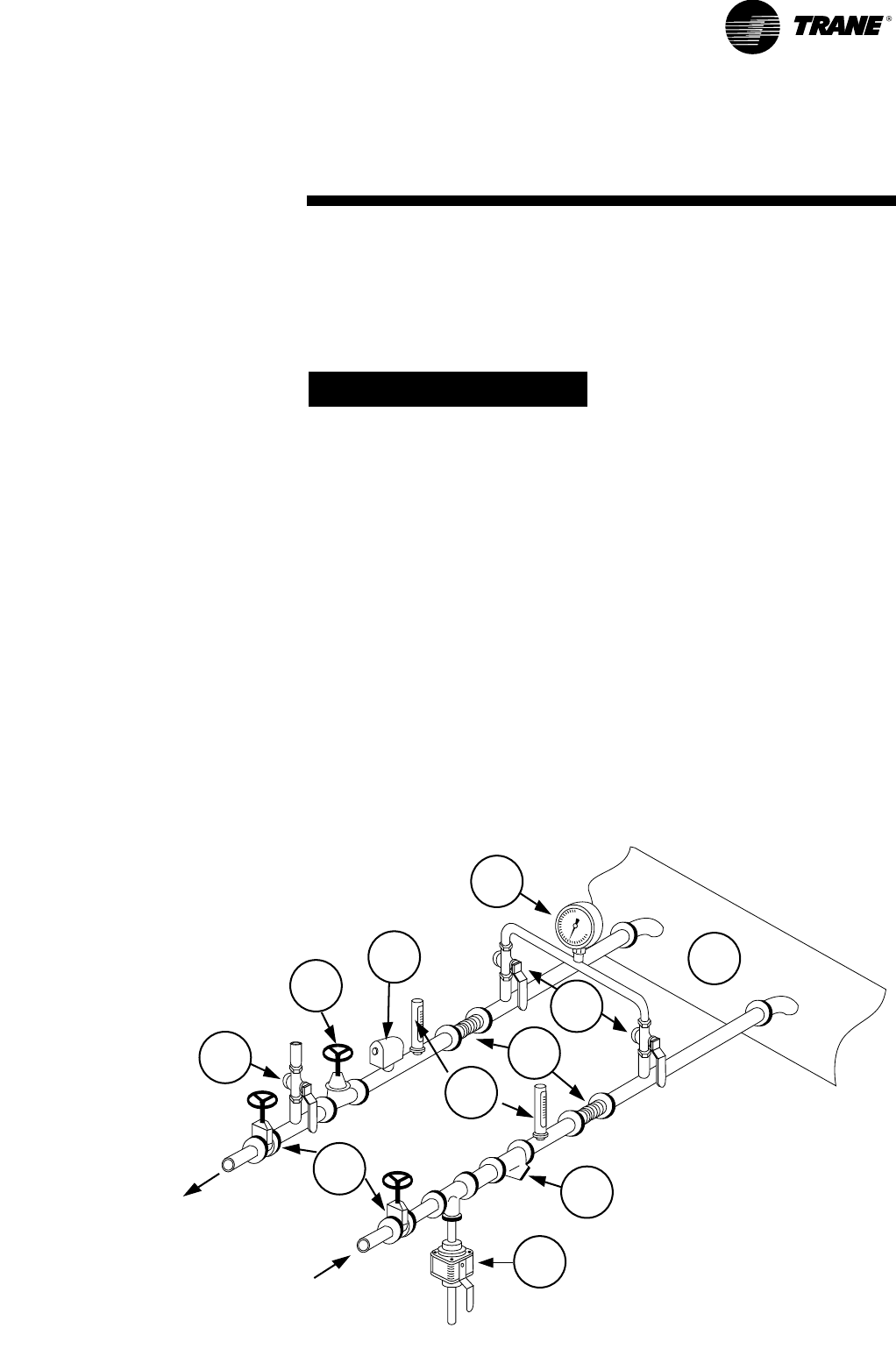
Figure 7 - Typical piping of the evaporator (RTUB)
1 Air vent
2 Balance valve
3 Flow switch
4 Thermometers
5 Expansion joints
6 Stop valves
7 Manometer
8 Evaporator
9 Filter
10 Drainage
RLC-SVX03A-E4