


28 TRG-TRC004-EN
notes
period two
Compressor Capacity Control
methods of capacity control, many of them function in a manner similar to the
inlet vanes presented in this section of the clinic.
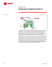
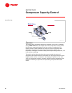
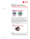
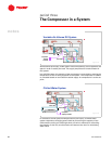
Inlet vanes “preswirl” the refrigerant before it enters the impeller. By
changing the refrigerant’s angle of entry, these vanes lessen the ability of the
impeller to take in the refrigerant. As a result, the compressor’s refrigerant-
pumping capacity decreases to balance with the evaporator load.
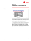
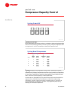
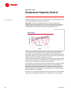
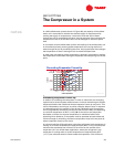
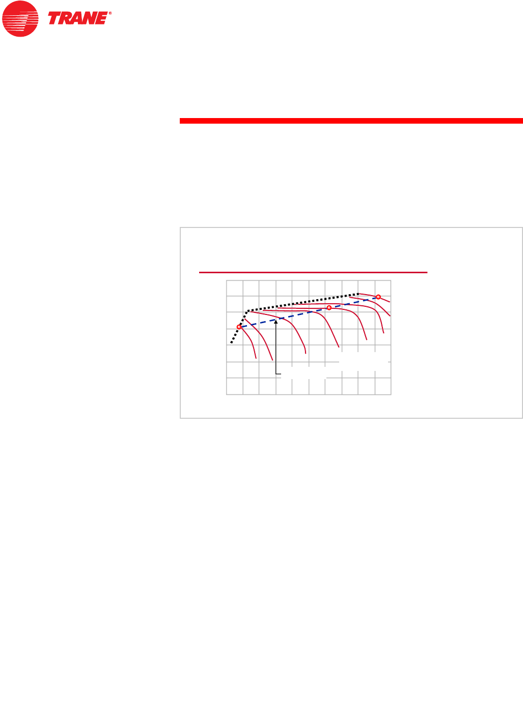
These curves represent the performance of a typical centrifugal compressor
over a range of inlet vane positions. The pressure difference between the
compressor inlet (evaporator) and outlet (condenser) is on the vertical axis and
compressor capacity is on the horizontal axis. The surge region represents the
conditions that cause unstable compressor operation.
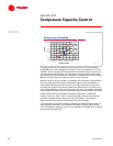
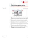
As the load on the compressor decreases from the full-load operating point (A),
the inlet vanes partially close, reducing the flow rate of refrigerant vapor and
balancing the compressor capacity with the new load (B).
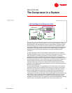
Less refrigerant, and therefore less heat, are transferred to the condenser. Since
the available heat rejection capacity of the condenser is now greater than
required, the refrigerant condenses at a lower temperature and pressure. This
reduces the pressure difference between the evaporator and the condenser.
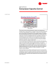
Continuing along the unloading line, the compressor remains within its stable
operating range until it reaches C.
Inlet vanes on a centrifugal compressor allow it to unload over a broad capacity
range while preventing the compressor from operating in the surge region.
,QOHW9DQHV
SUHVVXUHGLIIHUHQFH
SUHVVXUHGLIIHUHQFH
FDSDFLW\
FDSDFLW\
V
X
U
J
H
V
X
U
J
H
$
XQORDGLQJOLQH
XQORDGLQJOLQH
YDQHSRVLWLRQ
YDQHSRVLWLRQ
GHJUHHV
GHJUHHV
&
%
Figure 40