11
4. Installation and Operation
4.3 Installation and Start-Up
4.3.1
Connect the unit to the batteries per Section 3. Ensure that the nominal DC battery voltage is 12V.
4.3.2
Connect the unit to the AC load. Then connect to the AC source. Conrm that all wiring is correct and terminal is tight.
4.3.3
Press the ON/OFF button. The system will start working after a few seconds. If the AC source power fails, the unit will work in
Inverter mode. Otherwise, the system will switch to AC Mode and will power the load while charging the battery.
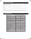
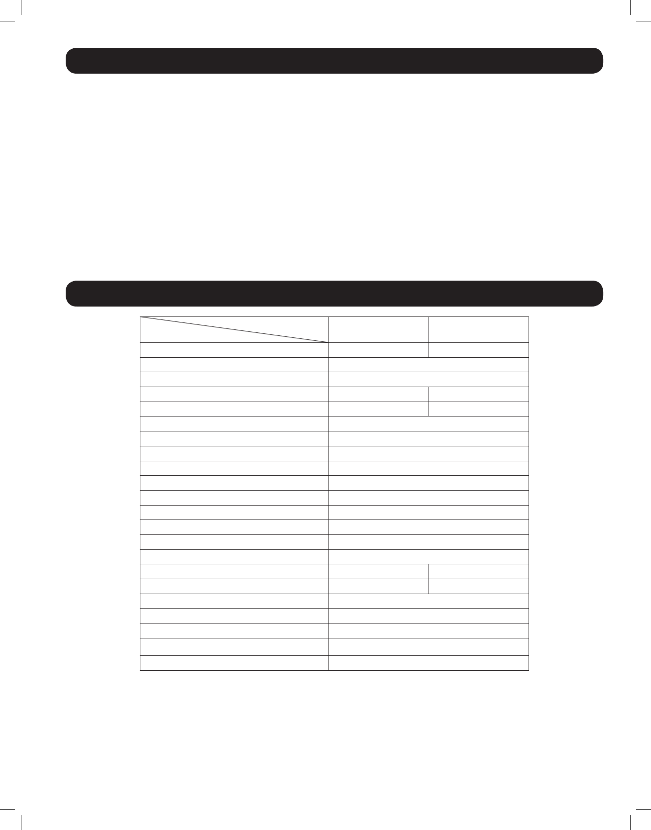
5. Technical Specifications
Model
Specification
APSX1012SW APSX2012SW
Continuous Power 1000 Watts 2000 Watts
Peak Inverter Efciency >82%
Output Waveform Sine Wave
DC Current at Rated Power 120 Amps 240 Amps
Recommended Battery Fuse 200 Amps 400 Amps
Nominal Input Voltage 12 VDC
DC Input Voltage Range 10.0 ~ 16 VDC
Low Battery Protection (Heavy/Light Load) 10.9/11.2 VDC
DC Mode Output Voltage Regulation +/- 10%
Power Factor Allowed 0.8 to 1
Frequency Regulation 50/60 Hz, +/- 0.5 Hz (Autoselect)
Standard Output Voltage 230 VAC
Load Sensing (Power Saving) 100W
Transfer Time 16 ms max
Forced Air Cooling Variable Speed
Automatic Transfer Relay 15A 30A
Adjustable Charge current 4 ~ 40 A 6 ~ 60 A
Resistive Load 100%
Inductive Load YES
Motor Load YES
Rectier Load YES
Wall-Mounting YES
201110117 93-3054.indb 11 11/9/2011 10:57:58 AM


