


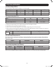
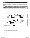

12 Volt Inverter/Charger
12 Volts
12 Volts
12 Volt Main Battery Connection
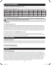
12 Volt Inverter/Charger
12 Volts
12 Volts
12 Volts
12 Volt Main and Auxiliary (House)
Battery Connection (Isolated Parallel)
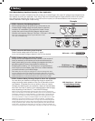
1 2
3
3
4
7
7
5
1
6
2
2
5
9
1
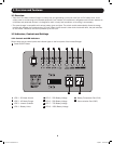
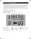
12-Volt Alternator
2
Vehicle Battery Ground
3
12-Volt Main Battery
4
12-Volt Auxiliary (House) Battery
5
UL-Listed Fuse & Fuse Block (mounted within 18 inches of the battery)
6
Battery Isolator
7
Large Diameter Cabling
3. Battery
• Connect Fuse: NEC (National Electrical Code) article 551 requires that you connect all of your Inverter/Charger’s positive
DC Terminals directly to a UL-listed fuse(s) and fuse block(s) within 18 inches of the battery. The fuse’s rating must equal
or exceed the minimum DC fuse rating displayed on the Inverter/Charger’s nameplate. See diagrams below for proper fuse
placement.
WARNING! • Failure to properly ground your Inverter/Charger to a vehicle’s chassis or earth ground
may result in a lethal electrical shock hazard.
• Never attempt to operate your Inverter/Charger by connecting it directly to output from an
alternator rather than a battery or battery bank.
• Observe proper polarity with all DC connections.
3.4.2 Non-Vehicular or Vehicular
Your Inverter/Charger’s Nominal DC Input Voltage must match the voltage of your battery or batteries—12 volts in most
vehicular applications.
It is possible to connect your Inverter/Charger to the main battery within your vehicle’s electrical system. In most vehicles,
the Inverter/ Charger will be connected to one or more dedicated auxiliary (house) batteries, isolated from the drive system to
prevent possible draining of the main battery.
201110117 93-3054.indb 9 11/9/2011 10:57:57 AM