


5
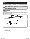
1. Overview and Features
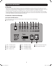
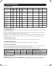
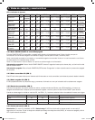
1.2.7 Battery Voltage (LED 5-8)
LED 5-8 indicate the battery capacity as detailed in the following table:
Battery Voltage LED 5 LED 6 LED 7 LED 8
25% On — — —
50% On On — —
75% On On On —
100% On On On On
1.2.8 Voltage Setting (Switch 1-3)*
Switch ON OFF
DC-to-AC Transfer Delay (Switch 1) 30 sec (Default) 5 sec
Low Battery Alarm (Switch 2) 11.2V 10.9V (Default)
AC Transfer Voltage (Switch 3) 190V 170V (Default)
* Notes:
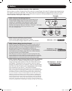
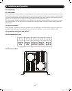
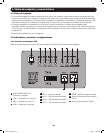
1. Switches are located farthest from the battery temperature port. See diagram on page 3.
2. The switches must be set before the system is turned on.
3. Switch 2 sets the low battery voltage alarm level (at higher voltage setting, alarm will sound sooner).
4. Switch 3 sets the low-level AC-to-DC voltage point. If the AC input voltage decreases to below the setpoint, the inverter will
automatically switch to DC MODE. See the following table for details.
Nominal Voltage Low Voltage Transfer Point (AC-to-DC) Return Voltage Point (DC-to-AC)
230V
On 190 200
Off 170 180
1.2.9 Search Mode Setting (Switch 4)
Search Mode activates when the unit is operating in inverter mode (battery power) to prevent unnecessary battery discharge
when electrical power is not required. If the inverter is supporting loads that must constantly be powered, turn off switch 4 to
disable Search Mode.
Switch 4 Search Mode Function
ON Enable Inverter turns on only if load is >100W
OFF (Default) Disable Inverter always on if AC power is absent
1.2.10 Floating Voltage/Battery Type (Switch 5)
Switch 5 Floating Voltage Acceptance Voltage Battery Type
ON (Default) 13.8V 14.5V Absorbed Glass Mat (AGM)
OFF 13.2V 13.8V Wet-Cell
Note: The unit will charge the battery to acceptance voltage, continue for 1 to 12 hours, then drop to floating voltage.
201110117 93-3054.indb 5 11/9/2011 10:57:55 AM