


GB
8
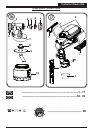
TexPerfect Flexio 525
2. If the feed rate is too low even at maximum flow setting, dilute in steps of 5 - 10 %
until the feed rate meets your requirements (observe the maximum permitted
dilution as stipulated by the manufacturer).
11. Start-up
Before connecting to the mains supply, be sure that the supply voltage is identical with
the value given on the rating plate.
•
Unscrew the container from the spray gun.
•
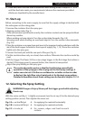
Aligning suction tube. (Fig. 2)
If the suction tube is positioned correctly, the container contents can be sprayed without
almost any residue.
When working on lying objects: Turn the suction tube forwards. (Fig. 2 A)
Spraying work when working on overhead objects: Turn the suction tube rearwards.
(Fig. 2 B)
•
Place the container on a paper base and pour in the prepared coating substance with the
aid of the feed hopper included in the scope of supply (Fig. 1, 15). Screw the container
tightly onto the spray gun.
•
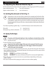
Connect the front part with the rear part of the gun (Fig. 3).
•
Put the machine down only on a level, clean surface. Otherwise the machine could tip
over!
•
Pull the trigger. The Flexio 525 has a two-stage trigger. In the rst stage the turbine is
started. If the trigger guard is pressed further, the material is transported.
•
Adjust the spray setting on the spray gun.
i
The enclosed practice poster is ideal for familiarising yourself with
operation of the spray gun. After trying out the rst spray coatings, it
makes sense to test it further on cardboard or a similar surface in order
to nd out the right ow rate of paint and air for the best spray pattern.
Detailed information about these settings can be found in chapter 12-14.
12. Selecting the Spray Setting
WARNING! Danger of injury! Never pull the trigger guard while adjusting
the air cap.
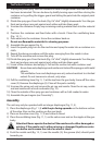
With the union nut (g. 4, 1) slightly unscrewed, turn the air cap (2) to the desired spray
setting position (arrow). Then tighten the union nut.
Fig. 3 A = vertical at jet
for applying the material horizontally
Fig. 3 B = horizontal at jet
for applying the material vertically
Fig. 3 C = circular jet
for corners, edges and hard-to-reach
surfaces