


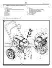

ProSpray 3.39 15
GB
Remedy in case of faults
Digital Electronic Spray Control (DESC) Error Messages
The following error message screens appear whenever the Digital Electronic
Spray Control (DESC) detects a problem with the sprayer. Once a problem
occurs and the error message appears, the sprayer will shut down.
Before proceeding, relieve any pressure remaining in the
system (valve position PRIME k). Additionally, follow all
other warnings to reduce the risk of an injection injury,
injury from moving parts or electric shock. Always unplug
the sprayer before servicing!
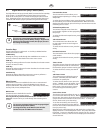
Check Transducer Screen
CHECK
TRANSDUCER
The Check Transducer screen appears when
the transducer has become disconnected or
is defective. Take the sprayer to a Wagner
authorizedservicecenterforrepair.
Check Motor Screen
CHECK
MOTOR
The Check Motor screen appears when the
motor or motor sensor is defective. Take the
sprayertoaWagnerauthorizedservicecenter
for repair.
Low Voltage Screen
LOW
VOLTAGE
TheLowVoltagescreenappearswhenthe
sprayer shuts down because of low input
voltage. Check the power supply and correct
the problem. Restart the sprayer.
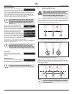
High Motor Temperature Screen
HIGH MOTOR
TEMPERATURE
The High Motor Temperature screen appears
when the temperature of the motor has risen too
high.TakethesprayertoaWagnerauthorized
service center for repair.
High Control Temperature Screen
HIGH CONTROL
TEMPERATURE
The High Control Temperature screen appears
when the temperature of the Digital Electronic
Spray Control (DESC) has risen too high. Take
thesprayertoaWagnerauthorizedservicecenterforrepair.
High Mechanical Load
HIGH MECHANICAL
LOAD
The High Mechanical Load screen appears when
the sprayer shuts down because of high current
or when the sprayer goes into current fold back
mode.TakethesprayertoaWagnerauthorizedservicecenterforrepair.
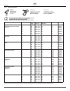
Type of malfunction
A. Unitdoesnotstart
B. Unitdoesnotdrawinmaterial
C. Unitdrawsinmaterial,butthe
pressure does not build up
D. Coating material exits at the top of
the uid section
E. Increased pulsation at the spray
gun
F. Poor spray pattern
G. Unitlosespower
Possible cause
1. No voltage applied.
2. Pressure setting too low.
3. ON/OFF switch defective.
1. ReliefvalveissettoSPRAY(p spray).
2. Filter projects over the uid level and
sucks air.
3. Filter clogged.
4. Suction hose/suction tube is loose, i.e.
the unit is sucking in outside air.
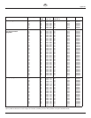
1. Tip heavily worn.
2. Tip too large.
3. Pressure setting too low.
4. Filter clogged.
5. Coating material ows through the
return hose when the relief valve is in
theSPRAY(p spray) position.
6. Packings sticky or worn.
7. Valveballsworn.
8. Valveseatsworn.
1. Upperpackingisworn.
2. Piston is worn.
1. Incorrect high-pressure hose type.
2. Tip worn or too large.
3. Pressure too high.
1. Tip is too large for the coating
material which is to be sprayed.
2. Pressure setting incorrect.
3. Volumetoolow.
4. Coating material viscosity too high.
1. Pressure setting too low.
Measures for eliminating the malfunction
1. Check voltage supply.
2. Turn up pressure control knob.
3. Replace.
1. Set relief valve to PRIME (k circulation).
2. Rell the coating material.
3. Clean or replace the lter.
4. Clean connecting points. Tighten suction tube.
1. Replace
2. For selection of a smaller tip, see Tip table on Page 20.
3. Turn pressure control knob clockwise to increase.
4. Clean or replace the lter.
5. Remove and clean or replace relief valve.
6. Remove and clean or replace packings.
7. Remove and replace valve balls.
8. Remove and replace valve seats.
1. Remove and replace packing.
2. Remove and replace piston.
1. Only use WAGNER original-high-pressure hoses in order
to ensure functionality, safety and durability.
2. Replace tip.
3. Turn pressure control knob to a lower number.
1. Replace tip, see Tip table on Page 20.
2. Turn pressure control knob until a satisfactory spraying
pattern is achieved.
3. Clean or replace all lters.
4. Thinoutaccordingtothemanufacturer’sinstructions.
1. Turn pressure control knob clockwise to increase.
9. Remedy in case of faults