


18 ProSpray 3.39
GB
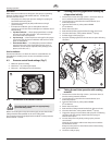
Repairs at the unit
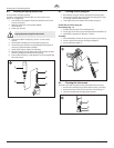
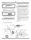
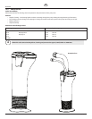
19. Insert upper packing (Fig. 17) with O-ring (1) and protruding
lip (2) downward.
1
2
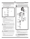
20. Insert upper support ring (9) on top of the upper packing (10)
21. Thread the upper seal retainer (8) into the upper housing (2).
22. Rotate the upper housing in the vise so that the bottom end is
facing up.
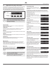
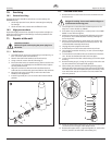
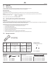
23. Insert the lower packing (Fig. 18) partially into the bottom of
the cylinder with the large beveled edge (1) facing toward the
cylinder (beveled edge will be facing up when the cylinder is
upright).
1
24. Push the lower packing assembly (Fig. 16, Item 12) into
position using the lower packing insertion tool (see Fluid
Section Assembly parts list for lower packing insertion tool
P/N).
i
Coat the piston insertion tool (i.e. upper packing
pre-form tool) and the piston rod with grease before
inserting them into the upper housing.
25. Place the piston insertion tool over the top of the piston rod
(6).
26. Insert the piston rod (6) into the bottom of the upper housing
(2), through the lower packing assembly (12), through the
upper packing assembly (10), and out through the upper seal
retainer (8).
i
Make sure the raised lip on the bottom of the lower
packing is fully outside the packing around the
piston rod after insertion of the piston rod.
27. Remove the piston insertion tool from the top of the piston
rod (6).
28. Lubricatethethreadsontheupperhousingwithanti-seize
compound. Remove the upper housing from the vise.
29. Insert the piston rod into the extension slider. When the
connecting pin hole on the piston rod lines up with the hole in
the extension slider, insert the connecting pin.
30. Thread the upper housing into the cylinder, turning clockwise.
31. Continue to turn the upper housing clockwise until it is ush
against the cylinder.
32. Replace the cylinder (3) back into the uid section clamp on
the gear housing. Make sure to slide the top of the piston rod
extension into the T-slot (13) on the slider assembly (14).
33. Push the lever on the underside of the unit toward the rear of
the sprayer to lock the uid section back into place.
34. Insert the adapter (Fig. 16, item 11) into the bottom of the
upper housing.
35. Making sure that the bearing ring (Fig. 14, item 3) and O-rings
(Fig. 14, items 4-5) are lubricated and in place, reassemble the
inlet valve assembly and and thread it into the upper housing.
Tighten the inlet valve housing until the o-ring engages,
then continue to tighten until snug. Once snug, tighten an
additional 1/8–1/4 turn.
36. Replace the connection hose to the tting on the high-
pressure lter.
37. Replace the return hose into the clamp on the siphon tube.
38. Install front cover.
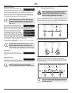
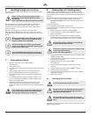
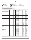
11.4 ProSpray 3.39 connection diagram
EMI Filter
P/N 0522052
P/N 0522053
Ground
Ground
Switch
Blue / White
Blue / White
Blue / White
Black /
Brown
Black / Brown
Black / Brown
Black
Green / Yellow
Green /
Yellow
Green /
Yellow
White
Blue / White
BlueBrown
Ground
Surge suppressor
P/N 0522058
White
White
Red
Black
Black
Fuse block
Fuse
Motor
Fan
Capacitor
Motor controller
Pressure sensor
Display wire
assembly (P/N 0522022)
L.E.D.
Hall sensor
Potentiometer
Black
Red
Red (+)
Black (-)
Power Cord