


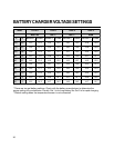

24
Do not connect incoming AC from any
source to the AC output of the inverter/
charger. This is known as backfeeding and
will damage the unit and void the warranty.
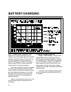
The Over Temp/Overload and Low Battery
LEDs will be blinking rapidly if this
condition exists.
WARNING
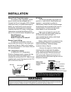
Grounding
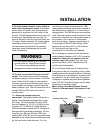
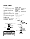
For safety purposes, the chassis of the
inverter/charger must be connected to your AC
ground system. Use 8 AWG bare copper or
green insulated wire, strip one end and use a
screwdriver to secure it to the chassis ground
bonding lug on the side of the unit. This wire
will connect to the ground in your AC electrical
system. Make sure the connection is clean
and tight.
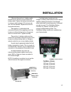
The system AC ground bonding terminal
is located on the front of the unit under the
wiring cover at the bottom of the unit. This
connector is for the bare copper or green
ground wires from the AC branch circuit supply
and to the AC loads or distribution panel. It is
important that these AC input and AC output
ground wires connect to the AC ground bus in
the circuit breaker panels.
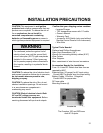
Some installations require heavier
grounding wire. Conform to local and national
electrical codes.
More information on grounding can be
found in the National Electrical Code and
local electrical codes.
INSTALLATION
Note: The battery cables are not
connected to the AC ground strip or to the
chassis lug of the unit.
Neutral Bonding
For safety purposes and NEC code
requirements, the Freedom Combi unit
internally bonds the AC output neutral (white)
to the AC output ground (green), when the unit
is OFF or in the inverter mode. When incoming
AC power is applied and the transfer switch is
engaged, the internal neutral-to-ground bond is
automatically lifted.
When external AC power is applied, the
grounding system is connected to the source
power ground, where neutral and earth ground
are bonded together. This technique ensures
safety in all conditions and conforms to the
requirements of the NEC.
Ground Lug