


5
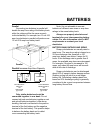
Circuit Breaker Protection
The Freedom Inverter/Charger is
supplemental breaker protected.
The INVERT/CHARGE breaker on the front
of the unit protects against sustained inverter/
charger over-current conditions.
These breakers are reset by pushing the
button back in.
The output circuit breakers protect the output
AC circuits. Models are available with one or
two outputs.
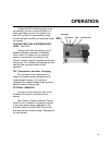
Thermostat Controlled Cooling
Freedom Inverter/Chargers are equipped
with a thermostatically controlled fan that cools
the unit so it can operate continually at its rated
units with only supplemental circuit breakers
between the unit and the load. Appropriate wire
gauges must be used throughout the installation.
Refer to NEC specifications.
THINGS YOU SHOULD KNOW
Inverter Idle Circuit
This automatic energy saving feature
reduces battery power consumption when no
AC load is present. Response from idle is
instantaneous. In most cases, the operation of
the idle circuit is not noticeable. Use of the
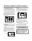
Remote Control Panel or Link Instrumentation
allows the idle threshold to be adjusted. The
unit does not put out 120 volts when in idle. To
bring the unit out of the idle condition, apply a
load.
Low and High Battery Shutdown
When in invert mode, if the battery
voltage drops to 10.0 volts, the inverter will
automatically shut off. Charge the batteries to
13.5 volts to automatically resume operation.
Voltage shutdown also occurs for a high
battery condition at 15.5 volts. Operation will
resume automatically when the battery voltage
drops below 15.5 volts. Check all DC sources
on the system for the reason for the excessive
voltage.
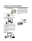
Power Sharing
When connected to an external AC
source the battery charger and transfer
functions are engaged. A unique Power
Sharing feature automatically reduces the AC
power consumption of the battery charger
allowing necessary AC power to go to the load.
This prevents the source AC INPUT circuit
breaker from tripping within the specified rating
of the AC circuit breaker.
The Power Sharing set point of each unit
has a factory default setting of 30 amps. This
can be changed using the Remote Control
Panel or Link Instrumentation.
25
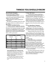
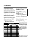
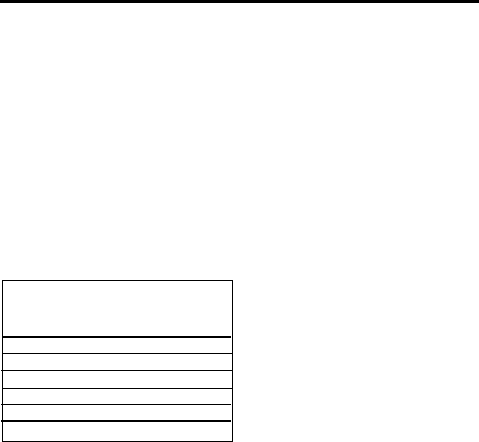
Circuit Breaker Protection
OUT 2
N/A
N/A
15/20*
N/A
15/20*
N/A
N/A
OUT 1
N/A
N/A
15/20*
N/A
15/20*
N/A
N/A
INV/CHG
15
20
20
25
25
30
30
10
15
15D
20
20D
25
30
*Circuit breaker configurations include 15/15,
15/20, and 20/20
*Note: Supplemental circuit breakers are reset
by pushing the button back in. The fault must be
removed before resetting the circuit breaker. Inte-
gral branch circuit rated breakers are reset by
setting the appropriate breaker switch to the “on”
position. The fault must be removed before re-
setting the circuit breaker.
If a 30-ampere service supplies the input to the
unit, a model with integral branch circuit rated
breakers allows direct wiring from the unit to the
load.