


39
INSTALLATION EXAMPLES
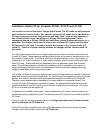
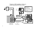
Installation examples for the new Freedom 458 Series Inverter/Chargers
Shorepower configurations:
Systems with one 30 Amp single-phase shorepower source with optional generator
Systems with two 30 Amp shorepower sources with optional generator
Systems with a 50 Amp 120 Volt single-phase (3 wire) shorepower source with optional
generator
Systems with a 50 Amp 120/240 Volt split-phase (4 wire) shorepower source with optional
generator
Inverter/charger configurations:
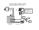
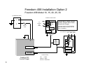
Single Input / Single Output Freedom 458 Model 10, 15, 20, 25, and 30
Single Input / Dual Output (Freedom 458 Model 15 S/D or 20 S/D only)
Dual Input / Dual Output Freedom 458 Model 20 D/D, 25 D/D and 30 D/D
· Can be connected with single in /single out mode
· Can be connected with dual in / single out mode
· Can be connected with dual in / dual out mode
The following installation examples are the most commonly used applications involving
specific shorepower connections, generator power options, and AC load configurations.
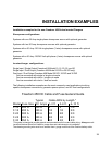
Freedom 458 DC Cable and Fuse General Guide
Typical Cable AWG by Length *
Model Fuse Size DC Amps 1–3 ft. 3–6 ft. 6–10 ft.
F-10 200 A 100 A 2 2 1/0
F-15 200 A 150 A 1/0 1/0 2/0
F-20 300 A 200 A 2/0 2/0 3/0
F-25 300 A 250 A 2/0 3/0 3/0
F-30 350 A 300 A 3/0 3/0 4/0
*This guide is intended to provide general recommendations for fuse and cable sizing. Always consult
Local and National Electrical Codes for proper fuse and cable size prior to installation.
The chassis grounding wire must be no smaller then 1 gauge under that of the Positive battery cable.