


48
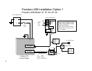
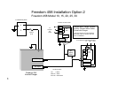
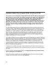
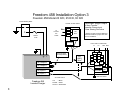
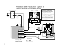
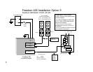
Installation Option #5 for Freedom 15 S/D and 20 S/D
The inverter is used in Single Input / Dual Output mode. The AC loads are split between
main loads and two branch circuits containing ‘inverter loads’ (AC output 1 and AC out-
put 2). The external sources of AC power can be a single 30 Amp shorepower source or
a 30 Amp breaker from a panel fed by a 50 Amp 120 Volt single phase (3 wire) shorepower
source, 1 leg of a 50 Amp 120/240 Volt split-phase (4 wire) shorepower source, or a gen-
erator. The charger shares power with the ‘inverter loads’ only.
In this installation example, one single-phase shorepower source is available or only one leg of a
split phase source is used to supply the AC input of the inverter/charger. It is highly
recommended that only the lighter appliance and outlet circuits be connected to the Inverter
branch circuits, AC Output 1 and AC Output 2. These loads are supplied power through the
inverter in charge/transfer mode, or by the inverter in invert mode. The charger shares power
with the ‘inverter loads’ only and can transfer up to 30 Amps. The heavier loads such as space
heaters, stove, water heater, air conditioners, AC to DC converters, or other battery chargers,
should remain connected to the Main AC Panel. These loads are only supplied by shore or
generator power from the main panel. This split load approach will help avoid problems such as
overloading the inverter or rapidly discharging the battery bank, and eliminate the need to
manually manage the energy usage of these loads when using inverter power.
The inverter AC input must be supplied power from a 30 Amp breaker in the main panel and from
the main neutral bus. The inverter has two AC outputs that are protected by internal branch rated
circuit breakers, eliminating the need for a separate sub panel. Two appliance and/or outlet
circuits are then supplied with power directly from the inverter AC outputs. All 15 Amp outputs
should use 12 or 14 gauge* wires for the output circuit, and all 20 Amp outputs should use 12
gauge wires*. Typically a GFI (GFCI) type outlet is used as the first outlet in the line. Consult
Local and National Electrical Codes for specific GFI installation recommendations.
If a generator is installed in the system, a break-before-make AC transfer switch is used to
select between shore or generator power. The transfer switch AC output is then routed to the
Main AC Panel.
*Always consult Local and National Electrical Codes for proper wire size prior to installation.