


1–16 975-0468-01-01
This guide for use by qualified installers only
There are two knockouts on the front panel for AC input and output
wiring.
When making the AC input and AC output connections, observe the
correct color code for the appropriate AC wire, as described in Table 1-5.
AC Input Connections
1. Ensure that AC and DC power are both OFF.
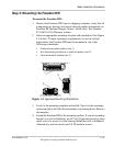
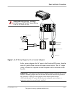
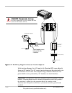
2. Install the required circuit breaker in the AC output panel supplying
the unit (See Figure 1-6 on page 1–21).
3. Remove the AC wiring compartment cover.
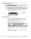
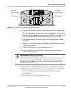
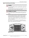
4. Remove the left-hand side AC wiring knockout from the front panel
of the unit (see Figure 1-5 on page 1–17).
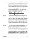
5. Locate the terminal block.
The two input terminals are labeled as follows:
• AC Input (L)
• AC Input (N)
A separate screw is provided to connect the AC input ground (see
Figure 1-5 on page 1–17).
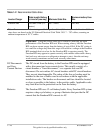
Table 1-4
Required AC wire size vs. required breaker rating
Required Breaker Size Required Wire Size
Freedom HW
30 A maximum 10 AWG
CAUTION: Equipment damage
The AC wiring terminal block is split into input and output sections. Damage to
the inverter will occur if the unit is wired incorrectly.
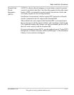
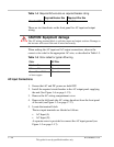
Table 1-5
Color codes for typical AC wiring
Color AC Wire
Black or Brown Line
White or Blue Neutral
Green, Green/Yellow,
or bare copper
Ground