


1–24 975-0468-01-01
This guide for use by qualified installers only
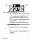
To make the DC connections
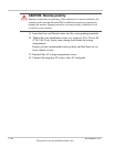
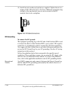
Refer to Figure 1-9.
1. Make sure the inverter is off and no AC or DC is connected to the
unit.
2. Remove the nuts and washers from the Freedom HW positive and
negative DC terminals.
3. Strip 1/2 inch (13 mm) to 3/4 inch (19 mm) insulation from one end
of each cable. The amount stripped off will depend on the terminals
chosen.
4. Attach the connectors that will secure the cables to the battery, to the
disconnect/battery selector switch, and the fuse block. The connectors
you use must create a permanent, low-resistance connection.
If crimp connectors are required, Xantrex recommends using
approved and certified connectors, and to use the tool recommended
by the terminal manufacturer. Make sure no stray wires protrude from
the connector or terminal.
(You may find it more convenient to have the crimp connectors
attached by the company that sells you the cable and/or connectors.)
5. For each cable end that will be connected to the inverter, strip 1/2 inch
(13 mm) to 3/4 inch (19 mm) of insulation from the cable. The
amount stripped off will depend on the terminals chosen.
6. Attach the connector that will join the cable to the inverter DC
terminal.
7. Install a fuse and fuse holder in the cable that will be used for the
positive side of the DC circuit.
The fuse must:
• be as close to the battery positive terminal as possible,
• be rated for DC circuits,
• have an Ampere Interrupting Capacity (AIC) that exceeds the
short-circuit current available from the battery (i.e., Class T fuse).
8. To prevent sparking when making the connection, ensure the
disconnect/battery selector switch is off.
9. Attach the connector on the positive cable to the positive DC terminal
on the inverter.