


Basic Installation Procedures
975-0468-01-01 1–17
This guide for use by qualified installers only
6. Strip about 2 inches (50 mm) from the jacket of the AC input cable.
The AC input cable may be either solid or stranded (as required), but
must have three conductors and be sized as in
Table 1-4 on page 1–16.
(The AC terminal block accepts wire sizes up to No. 10 AWG.)
7. Strip approximately 3/8 inch (10 mm) from the insulation of each
conductor.
8. Run the AC cable through the right-hand side knockout and into the
wiring compartment.
9. Fasten the Ground wire to the grounding screw.
10. Using the 1/8 inch slot screwdriver, loosen the wire attachment
screws on the terminals.
11. Insert the Line and Neutral wires into the corresponding terminals.
12. Tighten the wire attachment screws to a torque of 15.6–21.6 in-lbf
(1.76–2.44 N-m). Leave some wiring slack inside the wiring
compartment.
13. Reinstall the AC wiring compartment cover.
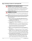
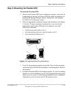
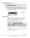
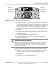
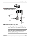
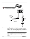
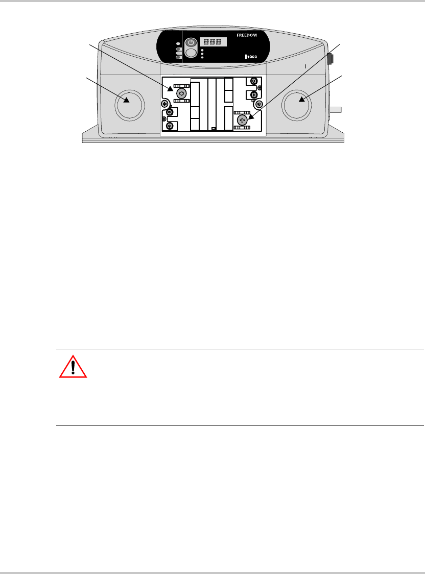
Figure 1-5
Freedom HW AC Wiring Compartment
Select
Utility
Battery
Fault
STATUS
Inp ut V oltage ( V )
Inp u tC ur re nt (A)
OutputPo we r (W )
AC INPUT
N
LGND
AC OUTPUT
N
LGND
CA UTI ON!
Do not connect theAC OUT to any
other source of power. Damage to unit may occur.
FREEDOM HW 1000
HW
AC knockout
AC output
ground screw
AC input
ground screw
AC knockout
CAUTION: Reverse polarity
Improper connections (connecting a line conductor to a neutral conductor, for
example) will cause the Freedom HW to malfunction and may permanently
damage the inverter. Damage caused by a reverse polarity connection is not
covered by your warranty.