


Basic Installation Procedures
975-0468-01-01 1–21
This guide for use by qualified installers only
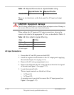
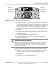
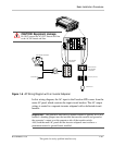
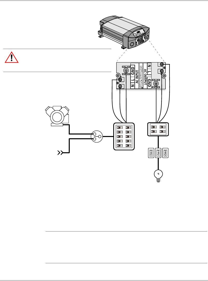
In this wiring diagram, the AC input to the Freedom HW comes from the
main AC panel which contains the input circuit breaker. The AC output
wiring is routed to a separate inverter subpanel with a dedicated circuit
breaker.
Figure 1-6
AC Wiring Diagram with an Inverter Subpanel
INVERTER SUBPANEL
AC OUTLETS (with GFCI)
MAIN AC PANEL
TRANSFER SWITCH
GENERATOR
SHORE POWER
INVERTER LOADS
See Important note below.
See Important
note below.
See Important
note below.
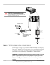
CAUTION: Equipment damage
Do NOT connect the AC OUT Neutral and Line
to the AC IN Neutral and Line.
Important:
The generator must have its neutral bonded to ground. If it is not
bonded, a bonding jumper must be installed between the neutral and ground at
the generator’s output or at the generator side of the transfer switch.
Also, both the main AC panel and the inverter subpanel must not have a
permanent neutral to ground bonds installed.