


Preparing for Installation
2–5
Wiring Requirements
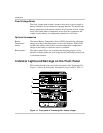
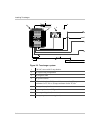
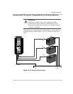
Figure 2-2 depicts a typical configuration system for the Truecharge+
showing the AC and DC wiring and protection devices required for a
successful installation.
DC Wiring
The DC wiring must meet the following requirements:
• Length and size
Use the largest recommended size rather than the minimum for best
performance and safety.
• DC Disconnect
The DC circuit from the battery to the charger must be equipped with
a disconnect and over-current protection device. The device usually
consists of a DC-rated circuit breaker, a “fused disconnect”, or a
separate fuse and disconnect. These devices must be rated for DC
voltage and current. Do not substitute devices rated only for AC
voltage: they may not operate properly.
• Over-current protection
The current rating must be matched to the size of the DC wiring used
and to the charger output, in accordance with the applicable codes.
The following recommended current ratings for the DC fuse or
breaker meet the requirements in ABYC, NEC, and CEC codes.
Truecharge 20+: 25 A
Truecharge 40+: 50 A
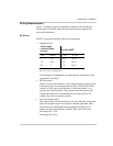
Wire Length
(
maximum length
one way
)
Wire Size AWG
a
a.Based on ABYC Recommended Practice
E-9, 75 °C wire, 3% voltage drop
feet meters TC 20+ TC 40+
5 1.5 No. 10 No. 8
7.5 2.25 No. 8 No. 6
20 3 No. 6 No. 6