


Introduction
1–8 975-0187-01-01
Preparing for Installation
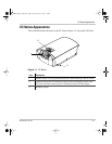
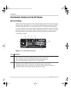
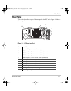
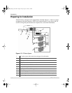
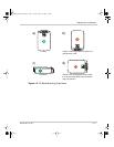
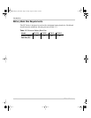
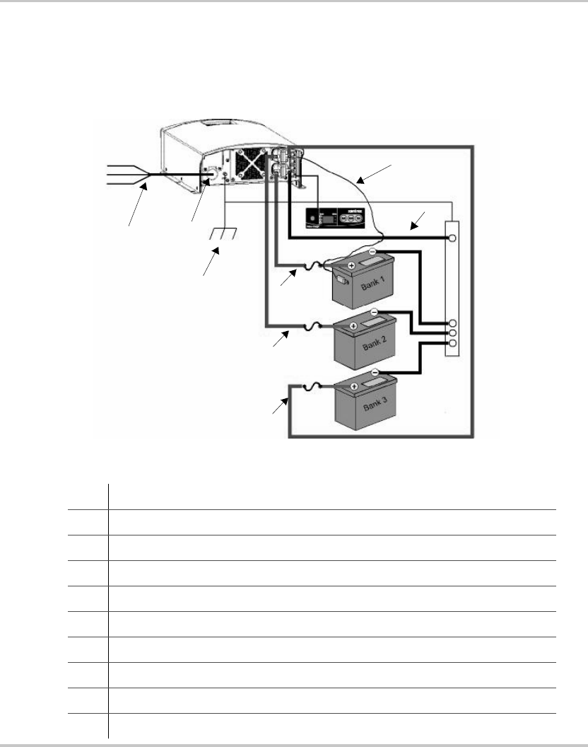
The XC Series is designed to be permanently mounted. Figure 1-1 shows a typical
installation with three batteries, a BTS and a remote display. It also shows the AC
and DC wiring and protection devices required for a successful installation.
Figure 1-5
XC Series System
1 AC mains source with correct size and type of circuit breaker
2 AC input wiring compartment
3 DC negative cable
4 DC positive cables
5 DC circuit breaker or DC fuse and disconnect
6 Battery or battery bank
7 Engine ground bus or DC negative bus
8 Remote display panel
9 Battery temperature sensor (#1 is standard equipment. #2 and #3 are optional)
10 DC chassis ground (earth)
L
N
G
1
2
3
4
4
4
5
5
5
6
6
6
7
8
9
10
XC_Charger_Owner.book Page 8 Friday, August 12, 2005 3:23 PM