


6 720 608 263
Installation instructions
17
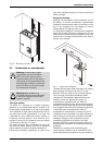
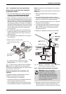
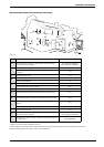
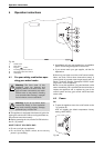
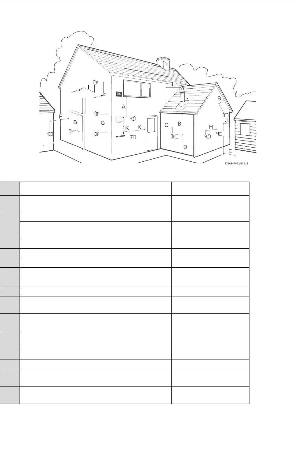
Recommended exhaust vent terminator clearances
Fig. 17
* Subject to local codes and anticipated snow level
** Other equipment that operates with a mechanical air inlet may require greater distances, reference manufacturer's instructions
NOTE: terminating exhaust vent under a deck is not recommended
Ref. Description Minimum distance
A
Directly below an opening; operable windows, doors and any non-
mechanical fresh air openings
36 in (twin pipe installation)
48 in (single pipe installation)
B
Below a gutter, sanitary pipework or eaves 24 in
Below a gutter, sanitary pipework or eaves, protected by metal
shielding
12 in
C From any internal corner 12 in
D*
Above ground or snow pack 12 in
Above a paved sidewalk 7 ft
E
From an opposing wall or structure facing the termination 24 in
From the relief valve of a gas regulator 36 in
F From a terminator facing a terminator 48 in
G Vertically between two exhaust vent terminators on the same wall 60 in
H Horizontally between two exhaust vent terminators on the same wall 12 in
I**
Horizontally and vertically from combustion air inlet of a twin pipe
system
36 in
From the gravity combustion air inlet any other equipment 48 in
J From any external corner 12 in
K
Horizontally from an opening; operable windows, doors and any non-
mechanical fresh air openings
12 in (twin pipe installation)
48 in (single pipe installation)
L
Vertically from a wall, roof slope, or obstruction (venting through a flat
or pitched roof)
see Chapter
3.6.5
Table 6