6 720 608 263
Maintenance and service
31
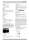
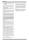
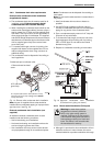
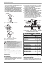
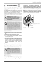
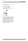
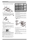
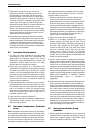
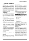
Fig. 43 Adjusting P2 CO
2
level
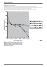
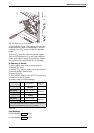
3. Verify both P1 and P2 CO
2
readings are within the
ranges specified in table 10. Repeat steps 1 and 2 as
necesssary until CO
2
values are within the specified
ranges.
4. Once CO
2
values are within the specified ranges,
verify the CO readings on P1 do not exceed 300ppm
(follow local codes). If values exceed this limit, inspect
vent system and fin coils (Chapter 5.1) for blockage.
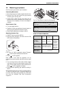
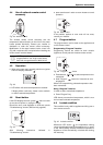
D. Returning to Service:
1. Return slotted screw cover to original position.
2. Reinstall Torx cover.
3. Remove CO
2
analyzer probe and reinstall flathead
screw with gasket in exhaust collar.
4. Install front cover.
5. Turn ON/OFF switch to the OFF (O) position and
then back to the ON (I) position.
6. Heater is ready for normal operation.
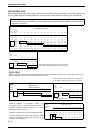
Final Readings
P2 CO
2
Reading: % CO
2
P1 CO
2
Reading: % CO
2
CO
2
level
Max CO
level
Nat. Gas
max. input P1 9.7 ± 0.3 %
300 ppm
min. input P2 9.5 ± 0.5 %
LP Gas
max. input P1 10.7 ± 0.3 %
300 ppm
min. input P2 10.5 ± 0.5 %
* Final reading must be confirmed with the front cover on,
CO
2
levels increase when the cover is installed.
Table 10