


6 720 608 263
Troubleshooting
33
6Troubleshooting
6.1 Introduction
Many of the questions customers ask regarding
operation of this unit can be answered by following the
troubleshooting steps as outlined below. Visit our web
site at www.boschhotwater.com
for more detailed
troubleshooting. For best results, perform each step
before proceeding to the next. The suggested solutions
may require that the cover be taken off. (See Page 5.
Fig. 3).
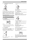
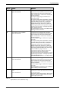
6.2 Burners do not ignite when hot
water is turned on
1. If the display is blank, verify power to electrical outlet.
(120VAC/60Hz properly grounded circuit required).
Verify that the heater on/off switch is in the on (I)
position.
2. Verify the fuses in the control unit are good.To
access fuses, the control unit must be removed. Go
to www.boschhotwater.com
for a detailed service
bulletin on this process. Two spare fuses are located
inside lower access panel of control unit.
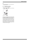
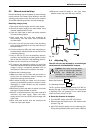
3. Make sure cold water inlet connection is plumbed to
the right side of heater when facing unit. See Fig. 25.
4. A minimum of 0.8 gallons per minute (GPM) (3 l/m)
is required to activate the heater. A quart container
should fill in 20 seconds or less to activate heater.
5. Clean inlet filter screen per chapter 5.1.
6. Inspect the water path for obstructions. Make sure all
showerheads, faucet aerators and whole house
filters are clear of debris.
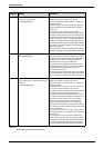
7. The heater activates when the water flow through the
unit is at or above the required minimum of 0.8 GPM
(3 l/m). A crossover creates back pressure on the
water flowing through the heater. Therefore, a higher
flow rate than normal is needed to force the heater to
activate. To check for a plumbing crossover, shut off
the cold water supply feed to the water heater. Then
open all of the hot water taps served by the heater.
Wait 10 minutes and check for water flow at taps.
There should be no water flowing. Any continuous
flow of water indicates a crossover is present and
must be corrected. Consult a professional plumber
for help in correcting a crossover. Failing single lever
faucets and mixing valves are common causes of
plumbing crossovers.
8. With the ON/OFF switch turned to OFF (O) position
and the power supply cord unplugged, remove the
unit's front cover (See Page 5. Fig 3). Check wire
connections between the water valve, control unit
and electrode set. See chapter 9.2 for location of
these parts.
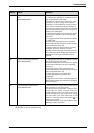
6.3 Water is too hot
1. Selected temperature on the unit is too high. To
lower output temperature, see chapter 4.3.
2. Clean inlet filter screen per chapter 5.1.
3. Inspect the water path for obstructions. Make sure all
showerheads, faucet aerators and whole house
filters are clear of debris.
4. Confirm the heater's gas type coincides with the type
of gas being supplied. See Fig. 2 for location of
rating plate.
5. This model is designed for cold water supply only.
For solar preheated applications, use of the model
125BS is recommended.
6. If the inlet cold water temperature is greater than
70°F due to geographic location avoid restrictive
outlets. Clean all showerheads and faucet aerators. It
may be necessary to upgrade to higher flow rate
fixtures if allowable by local code.
7. In areas where water has a high mineral content,
periodic descaling may necessary. See chapter 5.3
for directions.
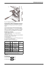
8. Ensure that both temperature sensors are making
contact and firmly mounted on their respective cold
and hot water pipes. The hot water sensor should be
located on the horizontal section of the hot water
pipe before it exits the heater. The cold water sensor
is located on the first horizontal section of pipe as the
water comes into the heater.
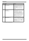
6.4 Water is not hot enough
1. Selected temperature on the unit is too low. To raise
output temperature, see chapter 4.3.
2. Clean inlet filter screen. See chapter 5.1.
3. Inspect the water path for obstructions. Make sure all
showerheads, faucet aerators and whole house
filters are clear of debris.
4. Confirm the heater's gas type coincides with the type
of gas being supplied. See Fig. 2 for location of
rating plate.
5. Check inlet gas particle screen for blockage at gas
inlet connection on bottom of unit.
6. Verify gas pressure is in accordance with
specifications in chapter 3.8. A gas pressure reading
is needed to proceed further. Contact your original
installer or a local certified gas technician to obtain
this reading.
Warning: If you are unable to perform
the tasks listed below, or need
additional assistance please contact
your original installer/licensed gas
technician.