


6 720 608 263
Maintenance and service
29
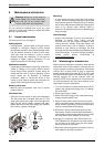
5.3 Mineral scale build-up
Periodic descaling may be necessary in areas with high
mineral content in the water. Scale buildup in the heat
exchanger may result in lower flow rates, error codes of
A7 and E9 and boiling sounds in the heat exchanger.
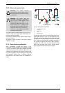
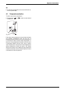
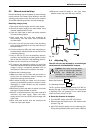
Descaling using a pump
1. Disconnect electrical supply from the water heater.
2. Shut off the water supply to the water heater using
(installer supplied) shut-off valve.
3. Open hot water taps to drain and relieve pressure
from the plumbing system.
4. Drain water from the unit's heat exchanger by
disconnecting inlet and outlet water connections
from the heater.
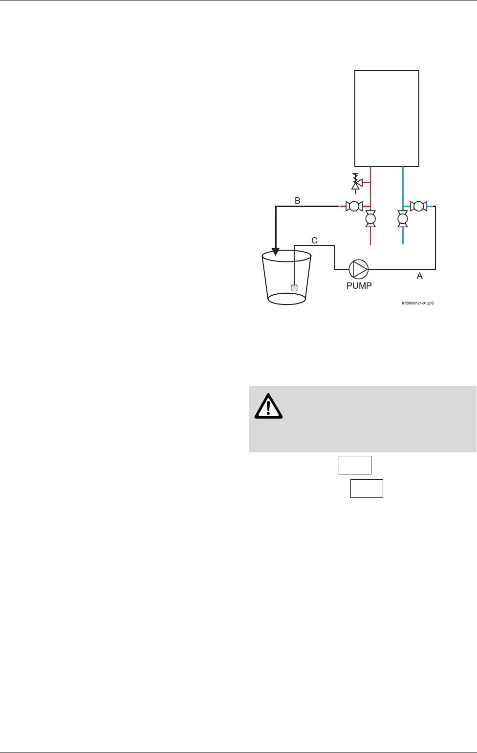
5. Connect a line (A) from the outlet of the circulating
pump (installer supplied) to the inlet water fitting on
the water heater.
6. Connect another line (B) to the water outlet fitting on
the water heater. Route the other end of this line into
a descaling reservoir.
7. Using a 3rd line (C) from the descaling reservoir,
connect to the inlet side of circulating pump. Install a
filter on the end of the line in the descaling reservoir.
8. Make sure all connections are "hand tight.".
9. Fill reservoir with descaling solution so both lines
inside are submersed. We recommend straight white
vinegar. If using a commercial descalant, refer to
manufacturer's instructions on dilution with water.
10.Operate the circulating pump.
11.Make sure there are no leaks and the solution is
flowing from the descaling reservoir through the
heater and returning to the reservoir.
12.Run solution through the heater until the solution
returning to the descaling reservoir comes out clear.
(Changing to a fresh solution may be necessary
during this process).
13.Disconnect all lines and drain all solution from heat
exchanger. Properly discard of solution.
14.Position a container below the hot water outlet and
reconnect cold water supply. Open cold water
supply shut-off valve and flush heat exchanger with
clean water.
15.Shut cold water shut-off valve and reconnect hot
water line to the water heater.
16.Reconnect electrical supply to unit, open water
isolation valves, and return the unit to service.
Fig. 39
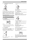
5.4 Adjusting CO
2
The CO
2
can only be adjusted by a certified gas
technician with a calibrated CO
2
analyzer.
Static Gas Pressure: “ WC
P1 Operating Pressure: “ WC
The P1 minimum operating gas pressure is 5" WC for
Natural Gas and 11"WC for Propane. Do not proceed
in adjusting CO
2
until pressure is at or above these
levels, but not to exceed 14” WC.
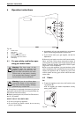
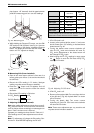
A. Once Gas Pressure is adequate
B Turn ON/OFF switch to the OFF (O) position.
B Remove brass flat head screw on the exhaust collar
as seen in Fig. 40.
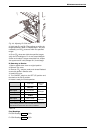
B Insert CO
2
analyzer probe into the measuring port.
The tip of the probe should be in the center of the flue
Caution: One factor that may affect
CO
2
levels is improper gas pressure.
Please see Chapter 3.8 for the
procedure to measure gas pressure
and record your findings below: