


6 720 608 263
30
Maintenance and service
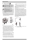
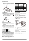
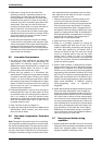
pipe (approx 1.5" inserted). Avoid air gaps between
probe and measuring port as it can alter readings.
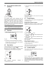
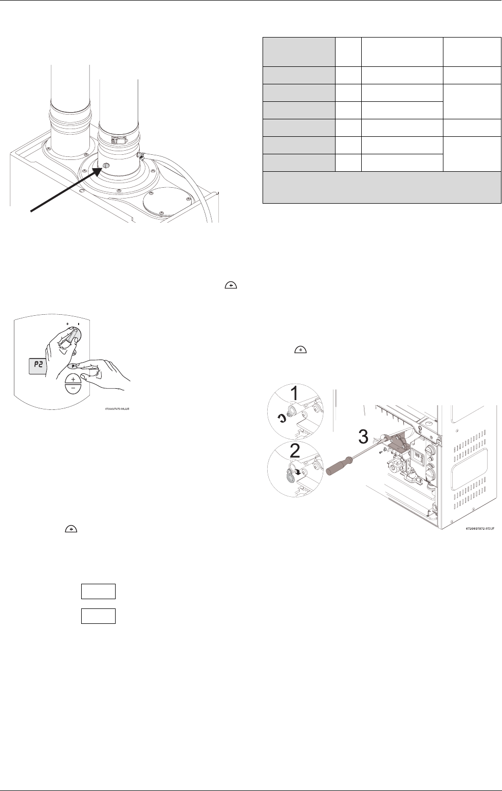
Fig. 40 Measuring port
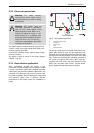
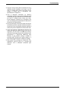
B While holding the Program (P) button, turn the ON/
OFF switch to ON (I) position (see Fig. 41). As soon
as ‘188’ flashes on the display, release the Program
button. The display should now read P2. Press
button until “P1” appears on display.
Fig. 41
B. Measuring CO
2
(Cover Installed):
B Open all hot water taps to achieve a flow rate of at
least 4 gallons per minute. (1 tub and 2 sinks should
be sufficient).
B Record the CO
2
reading in P1 below. (Analyzer
reading may take several minutes to stabilize).
B Press the ‘ ’ button until P2 appears. Unit will
ramp down to low fire and the water flow should
decrease.
B Record the CO
2
reading in P2 below.
P1 CO
2
Reading: % CO
2
P2 CO
2
Reading: % CO
2
C. Adjusting CO2 (cover removed):
Note: when making adjustments with the front cover off,
CO
2
values will be 0.3 - 0.5% lower than with the front
cover on. Adjust values accordingly to make target num-
bers in Table 10 when cover is secured.
Compare your readings to those found in Table 10. If
CO
2
readings are off, make adjustments as outlined
below.
Note: P1 adjustment will change the P2 reading. Con-
firm the P1 value BEFORE adjusting the P2 level.
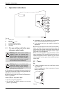
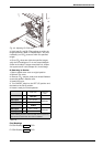
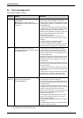
1. If P1 CO
2
level is off:
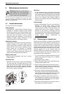
B Loosen yellow painted philips screw (1) and cover
should rotate down (2) revealing a recessed brass
slotted screw. Fig. 42.
B Turning the slotted screw counter clockwise will
raise P1 CO
2
levels and clockwise will lower P1
CO
2
levels. Adjustments to the slotted screw will
also change P2 CO
2
levels.
B After bringing the P1 CO
2
readings in range, press
the button to enter the P2 mode. Verify CO
2
readings in P2 mode.
Fig. 42 Adjusting P1 CO
2
level
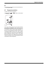
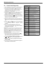
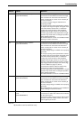
2. If P2 CO
2
level is off:
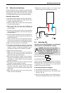
B Remove yellow painted #40 Torx cover from the front
of the gas valve. (Fig. 43) A plastic #40 Torx screw
will be revealed.
B Turning the plastic #40 Torx screw counter
clockwise will lower P2 CO
2
levels and clockwise
will raise P2 CO
2
levels.
Note: These screw adjustment are very sensitive and
may take several minutes to stabilize.
CO
2
level
Max CO
level
Nat. Gas
max. input P1 9.7 ± 0.3 %
300 ppm
min. input P2 9.5 ± 0.5 %
LP Gas
max. input P1 10.7 ± 0.3 %
300 ppm
min. input P2 10.5 ± 0.5 %
* Final reading must be confirmed with the front cover on,
CO
2
levels increase when the cover is installed.
Table 9