


-13-
3. COARSE ADJUSTMENT:
To make a large depth adjustment, depress
coarse adjustment release lever and raise or
lower to desired depth. There are three
notches in the motor housing which are
spaced 1/2" to facilitate this adjustment.
4. FINE DEPTH ADJUSTMENT:
To use the fine adjustment feature, turn the
fine adjustment knob clockwise to lower the
router bit or counter-clockwise to raise it.
NOTE: Be sure coarse adjustment lever is
engaged in one of the coarse adjustment
notches before making a fine adjustment.
To allow precise settings, the indicator ring is
graduated in English and Metric increments.
(Note: one full turn of fine adjustment knob =
1/16" or approximately 1.5 mm. The fine
adjustment mechanism has a total adjustment
range of 7/8" (23 mm). Each cast indicator
mark next to coarse adjustment lever is equal
to 1/8"
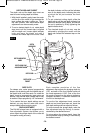
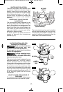
To prevent damage to tool, avoid wedging the
coarse adjustment lever against the upper A or
lower B portion of the housing as shown in
figure 10.
5. After making depth adjustments, re-clamp
the motor.
The indicator ring may be reset to zero without
moving the fine adjustment knob, to allow the
user to begin the adjustment from any
reference point desired.
When the router is installed in a router table,
it can be adjusted with a 1/8” hex wrench, not
included with all models. (See page 21).
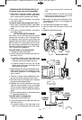
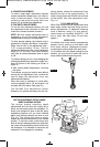
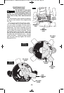
The RA1002 Fine Adjustment Control
Extension, an optional accessory for the non-
plunge bases, allows fine adjustment from
beyond the top of the motor housing. To
install, simply press the RA1002 into the end
of the base’s own fine adjustment knob.
(Fig. 11)
TO CLAMP MOTOR
When final coarse and fine adjustments have
been made, fasten the base clamp lever to
secure adjustments. (If additional clamping
force is desired: using a 10 mm wrench,
rotate clamp nut clockwise SLIGHTLY (1/8
turn or less), then test clamp. Do not over-
tighten.)
DEEP CUTS
For deeper cuts, make several progressively
deeper cuts by starting at one depth and
then make several subsequent passes,
increasing the cutting depth with each pass.
To be certain that your depth settings are as
desired, you may want to make test cuts in
scrap material before beginning work.
FIG. 11
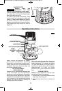
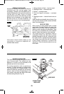
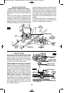
DEPTH ADJUSTMENT WITH PLUNGE
BASE PLUNGING ACTION
The plunge feature simplifies depth
adjustments and will allow the cutting bit to
easily and accurately enter the workpiece. To
lower, push plunge lock lever to the left, apply
downward pressure until you reach desired
depth, and release pressure on lever to lock
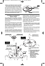
(Fig. 12). The plunge lock lever is spring
loaded and returns automatically to the locked
position. To raise the router, push plunge lock
lever to the left, release pressure on router and
the router will automatically retract the bit from
the workpiece. It is advisable to retract the bit
whenever it is not engaged in work piece.
FIG. 12
BM 2610018532 01-12:BM 2610018532 01-12.qxp 1/23/12 9:21 AM Page 13