


-22-
The undertable base accessory includes the
screws needed to fasten the base to a router
table mounting plate, as well as a T-hex
wrench for above-table depth adjustment.
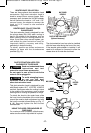
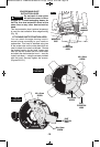
ATTACHING BASE TO
MOUNTING PLATE
Attach the RA1161 to the router table’s
mounting plate using either or both sets of
enclosed mounting screws.
The base has two sets of threaded holes for
mounting the base:
•Three 10-24 holes in industry-standard
3-hole pattern.
•Four M4 holes in Bosch 4-hole pattern.
Mounting screws required for the RA1161:
(not included with all models).
•Three 10-24 screws.
•Four M4 screws.
The length will depend on the thickness of
your router table or router table mounting
plate.
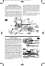
If your router table mounting plate does not
have countersunk holes in either of those
patterns, you will need to determine the hole
locations, drill and countersink them, also
locate and drill a hole for the over-table
adjustment wrench.
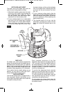
CONNECT THE ROUTER AND THE
ROUTER TABLE SWITCH
To prepare for use of the switch,
1. Make sure the router switch and the router
table switch are both turned off.
2. Plug the router table switch cord to wall
outlet.
3. Plug the router into the "pigtail" socket on
the router table switch.
4. Lock router switch on: squeeze trigger,
depress lock-on button, and release trigger.
5. Use the router table switch to start and stop
the router.
DEPTH ADJUSTMENT (See page 12-13)
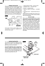
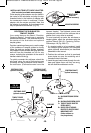
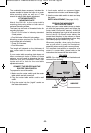
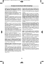
FEEDING THE WORKPIECE
ON A ROUTER TABLE
Always use your router table's fence or starter
pin and the appropriate guard and follow the
router table's instruction manual. ALWAYS
feed the workpiece from right to left across the
front of the bit. On Bosch router tables, the
correct feed direction is also shown on fence
housing and on the featherboards, when they
have been properly installed. (Fig. 29)
Whenever possible, when using the fence,
use a push stick to push the workpiece,
especially when working with narrow pieces.
For complete instructions on operation of a
router in a router table, please refer to the
instructions that come with the router table.
TOP VIEW
NOTE: For clarity, guard and featherboard
removed from drawing.
FIG. 29
WORKPIECE
DIRECTION
OF FEED
BIT
BEARING
FENCE FACE
FENCE FACE
BM 2610018532 01-12:BM 2610018532 01-12.qxp 1/23/12 9:21 AM Page 22